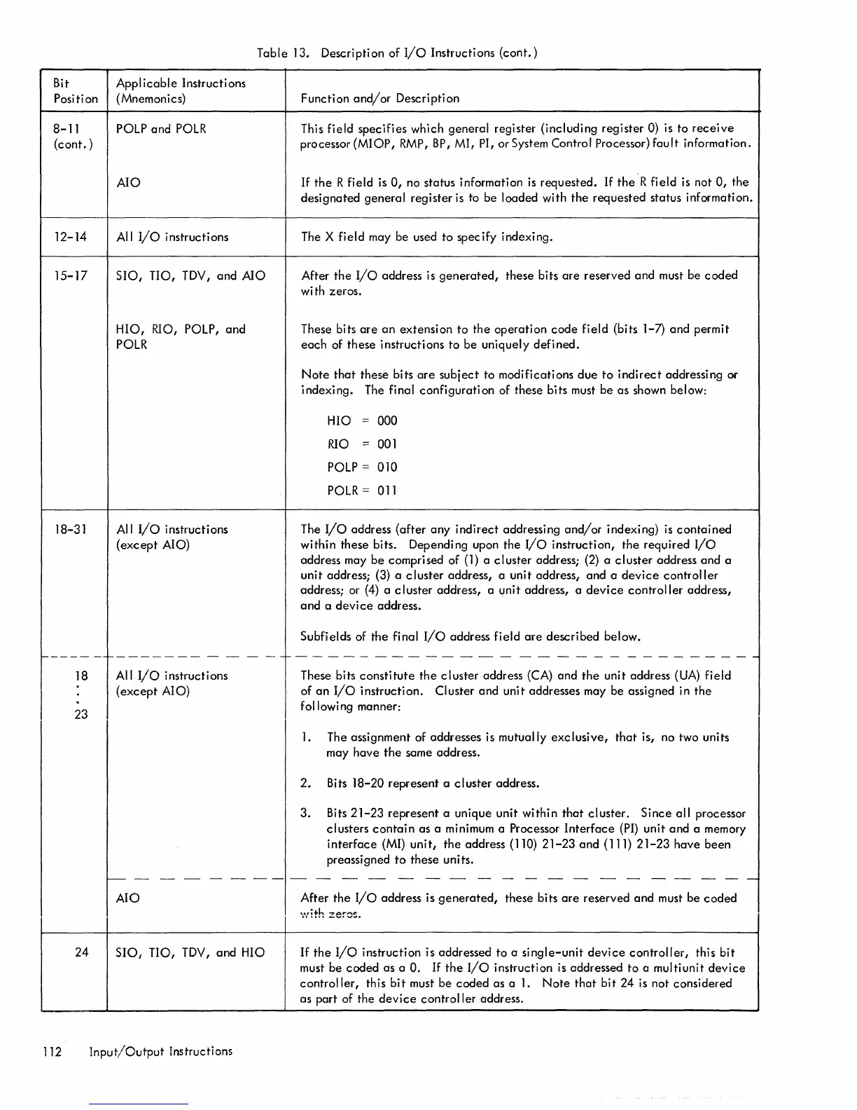
Table 13. Description of
I/O
Instructions
(cont.)
Bit
Applicable
Instructions
Position (Mnemonics)
8-
11
POLP
and
POLR
(cont.)
12-14
15-17
18-31
AIO
All
I/O
instructions
510,
TIO, TDV,
and
AIO
HIO,
RIO, POLP,
and
POLR
All
I/o
instructions
(except
AIO)
Function
and/or
Description
This
field
specifies which general register (including register 0) is to
receive
processor (MIOP,
RMP,
BP,
MI, PI, or System Control Processor)
fault
information.
If
the
R field
is
a,
no status information
is
requested.
If
the"R field
is
not
a,
the
designated
general
register
is
to be loaded with
the
requested status information.
The X field may be used to specify indexing.
After
the
I/O
address is
generated,
these bits
are
reserved
and
must be
coded
with zeros.
These bits
are
an
extension
to
the
operation
code
field
(bits 1-7)
and
permit
each
of these instructions
to
be uniquely
defined.
Note
that
these bits
are
subject
to modifications
due
to
indirect
addressing or
indexing.
The final
configuration
of these bits must be
as
shown below:
HIO = 000
RIO
= 001
POLP
=
OlO
POLR
= all
The
I/O
address
(after
any
indirect
addressing
and/or
indexing)
is
contained
within
these bits. Depending upon the
I/O
instruction,
the
required
I/O
address may
be
compri sed of
(1)
a
cluster
address; (2) a
cluster
address
and
a
unit
address; (3) a
cluster
address, a unit address,
and
a
device
controller
address; or
(4)
a
cluster
address, a unit address, a
device
controller
address,
and
a devi
ce
address.
Subfields of
the
final
I/o
address field
are
described
below.
f-----
-
~-------
- -
-"
-
-f--
- - - - - - - - - - - - - - - - - - - - - - - - - - -
18
23
All
I/O
instructions
(except
AIO)
These bits
constitute
the
cluster
address (CA)
and
the
unit address
(UA)
field
of
an
I/o
instruction. Cluster and unit addresses may be assigned in
the
following manner:
1.
The assignment of addresses is mutually
exclusive,
that
is, no two units
may have
the
same address.
2.
Bits
18-20
represent a
cluster
address.
3. Bits
21-23
represent a unique unit within
that
cluster.
Since
all processor
clusters
contain
as a minimum a Processor
Interface
(PI) unit
and
a memory
interface
(MI)
unit,
the
address (llO)
21-23
and
(111)
21-23
have been
preassigned
to
these units.
c----------------------
---
AIO
24
510,
TIO, TDV,
and
HIO
112
Input/Output
Instructions
After
the
I/o
address is
generated,
these bits
are
reserved
and
must be
coded
If
the
I/O
instruction is addressed to a
single-unit
device
controller,
this
bit
must be
coded
as
a
O.
If
the
I/O
instruction is addressed
to
a multiunit
device
controller,
this
bit
must be
coded
as a
1.
Note
that
bit
24 is not considered
as
part of
the
device
controller
address.
 Loading...


