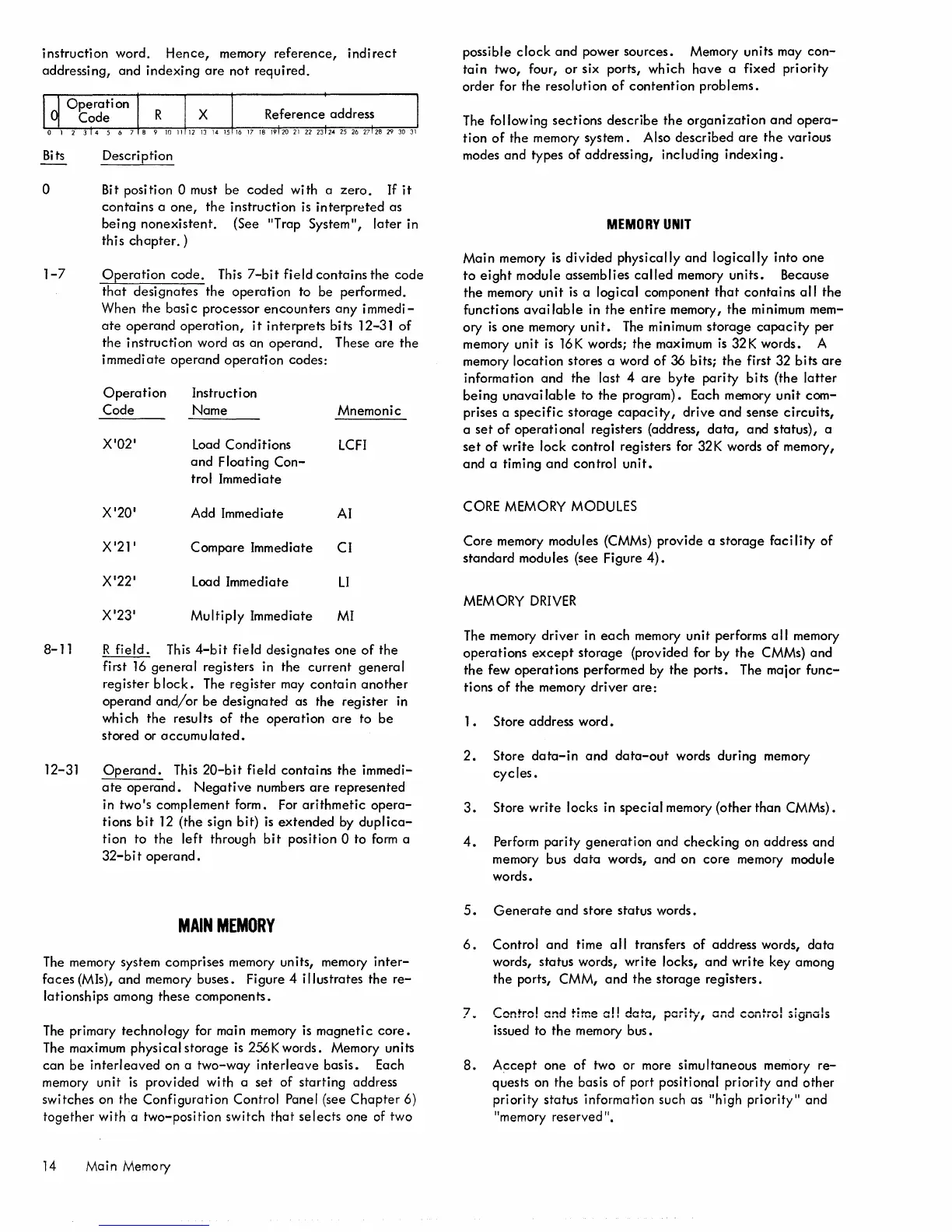
instruction
word.
Hence,
memory
reference,
indirect
addressing,
and
indexing
are
not
required.
Bits
o
1-7
8-11
12-31
Description
Bit position
0 must be
coded
with
a
zero.
If
it
contains
a
one,
the
instruction
is
interpreted
as
being
nonexistent.
(See "Trap System",
later
in
this
chapter.)
Operation
code.
This
7-bit
field
contains
the
code
that
designates
the
operation
to be performed.
When
the
basi c processor
encounters
any
i
mmedi-
ate
operand
operation,
it
interprets
bits 12-31
of
the
instruction
word as an
operand.
These
are
the
immediate
operand
operation
codes:
Operation
Code
X'02'
X'20'
X'21'
X'22'
X'23'
Instruction
Name
Load Conditions
and
Floating
Con-
trol Immediate
Add Immediate
Compare Immediate
Load Immediate
Multiply
Immediate
Mnemonic
LCFI
AI
CI
LI
MI
R
field.
This
4-bit
field
designates
one
of
the
first
16
general
registers in the
current
general
register
block.
The register may
contain
another
operand
and/or
be
designated
as the register in
which
the
results
of
the
operation
are
to
be
stored
or
accumulated.
Operand.
This
20-bit
field
contains
the
immedi-
ate
operand.
Negative
numbers
are
represented
in
two's
complement form. For
arithmetic
opera-
tions
bit
12
(the
sign bit)
is
extended
by
duplica-
tion to the
left
through
bit
position 0 to
form
a
32-bit
operand.
MAIN
MEMORY
The memory system comprises memory units, memory
inter-
faces
(MIs),
and
memory buses. Figure 4
illustrates
the
re-
lationships among
these
components.
The primary
technology
for main memory is
magnetic
core.
The maximum physical
storage
is
256Kwords.
Memory units
can
be
interleaved
on a
two-way
interleave
basis.
Each
memory
unit
is
provided with a
set
of
starting
address
switches on
the
Configuration
Control Panel (see
Chapter
6)
together
witha
two-position
switch
that
selects
one of two
14 Main Memory
possible
clock
and
power
sources.
Memory units may
con-
tain
two, four,
or
six ports, which
have
a fixed priority
order
for
the
resolution
of
contention
problems.
The following
sections
describe
the
organization
and
opera-
tion
of
the
memory system. Also
described
are
the
various
modes
and
types
of
addressing, including
indexing.
MEMORY
UNIT
Main
memory is
divided
physically
and
logically
into
one
to
eight
module assemblies
called
memory
units.
Because
the
memory
unit
is
a logical component
that
contains
all
the
functions
available
in
the
entire
memory,
the
minimum mem-
ory
is
one
memory
unit.
The minimum
storage
capacity
per
memory
unit
is
16K words;
the
maximum
is
32K words. A
memory
location
stores a word
of
36 bits;
the
first 32 bits
are
information
and
the
last 4
are
byte
parity
bits (the
latter
being
unavailable
to
the
program). Each memory
unit
com-
prises a
specific
storage
capacity,
drive
and
sense
circuits,
a
set
of
operational
registers (address,
data,
and status), a
set
of
write
lock
control
registers for 32K words
of
memory,
and
a timing
and
control
unit.
CORE MEMORY MODULES
Core
memory modules (CMMs) provide a
storage
faci lity
of
standard
modules (see Figure
4).
MEM
ORY
DRIVER
The memory
driver
in
each
memory
unit
performs
all
memory
operations
except
storage
(provided for by
the
CMMs)
and
the
few
operations
performed by
the
ports. The major
func-
tions
of
the
memory
driver
are:
1 • Store address
word.
2.
Store
data-in
and
data-out
words during memory
cycles.
3.
Store
write
locks in
special
memory (other than CMMs).
4.
Perform
parity
generation
and
checking
on address
and
memory bus
data
words, and on
core
memory module
words.
5.
Generate
and
store status words.
6.
Control
and
time
all
transfers
of
address words,
data
words, status words,
write
locks,
and
write
key among
the
ports, CMM,
and
the
storage
registers.
7.
Centre! end time o!! date,
pcr:f';1
and control signals
issued to
the
memory bus.
8.
Accept
one
of
two or more simultaneous memory
re-
quests on
the
basis
of
port positional priority
and
other
priority status information such as "high
priority"
and
"memory reserved
".

 Loading...


