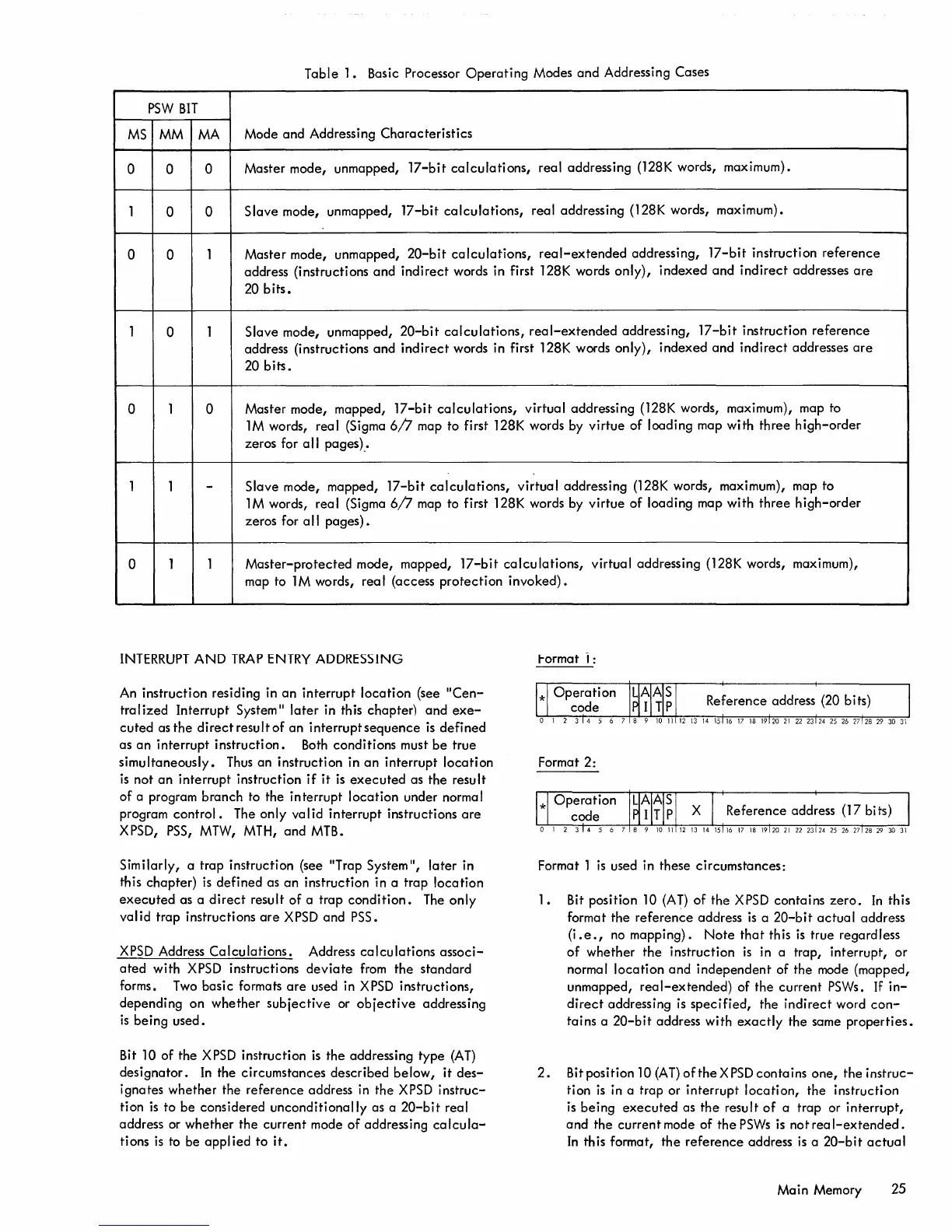
Table
1.
Basic Processor
Operating
Modes
and
Addressing Cases
PSW
BIT
MS
MM
MA
Mode
and
Addressing
Characteristics
0 0
0
Master mode, unmapped,
17-bit
calculations,
real
addressing (128K words, maximum).
1
0
0
Slave
mode, unmapped,
17-bit
calculations,
real addressing (128K words, maximum).
0
0
1
Master
mode, unmapped,
20-bit
calculations,
real-extended
addressing,
17-bit
instruction
reference
address (instructions
and
indirect
words in first 128K words
only),
indexed
and
indirect
addresses
are
20
bits.
1
0
1
Slave
mode,
unmapped,
20-bit
calculations,
real-extended
addressing,
17-bit
instruction
reference
address (instructions
and
indirect
words in first 128K words
only),
indexed
and
indirect
addresses
are
20
bits.
0
1
0
Master
mode, mapped,
17-bit
calculations,
virtual
addressing (128K words, maximum), map to
1M
words, real (Sigma
6/7
map to first 128K words by
virtue
of
loading map
with
three
high-order
zeros for
all
pages)
.•
1
1
-
Slave
mode,
mapped,
17-bit
calculations,
virtual
addressing (128K words, maximum), map to
1M
words,
real
(Sigma
6/7
map to first 128K words by
virtue
of
loading map
with
three
high-order
zeros for a
II
pages).
0 1
1
Master-protected
mode, mapped,
17-bit
calculations,
virtual
addressing (128K words, maximum),
map to 1 M words,
real
(access
protection
invoked).
INTERRUPT
AND
TRAP
ENTRY
ADDRESSING
An
instruction
residing in
an
interrupt
location
(see
"Cen-
tra I
ized
Interrupt
System"
later
in this
chapter)
and
exe-
cuted
as
the
di
rect
resu I t
of
an
interrupt
sequence
is
defi
ned
as
an
interrupt
instruction.
Both
conditions
must
be
true
simultaneously.
Thus
an
instruction
in
an
interrupt
location
is
not
an
interrupt
instruction
if
it
is
executed
as
the
result
of
a program
branch
to the
interrupt
location
under normal
program
control.
The only
valid
interrupt
instructions
are
XPSD,
PSS,
MTW, MTH,
and
MTB.
Similarly,
a
trap
instruction (see "Trap System",
later
in
this
chapter)
is
defined
as
an
instruction
in a
trap
location
executed
as
a
direct
result
of
a
trap
condition.
The
only
valid
trap
instructions
are
XPSD
and
PSS.
XPSD
Address
Calculations.
Address
calculations
associ-
ated
with
XPSD instructions
deviate
from
the
standard
forms.
Two
basic
formats
are
used in XPSD instructions,
depending
on
whether
subjective
or
objective
addressing
is
being
used.
Bit 10
of
the
XPSD instruction
is
the
addressing
type
(AT)
designator.
In
the
circumstances
described
below,
it
des-
ignates
whether
the
reference
address in
the
XPSD
instruc-
tion
is
to
be
considered
unconditionally
as a
20-bit
real
address or
whether
the
current
mode
of
addressing
ca
Icula-
ti ons
is
to
be
appl ied
to
it.
t-ormat
,:
Format 2:
Format 1
is
used in these
circumstances:
1.
Bit position 10
(AT)
of
the
XPSD
contains
zero.
In
this
format
the
reference
address
is
a
20-bit
actual
address
(i
.e.,
no
mapping).
Note
that
this
is
true regardless
of
whether
the
instruction
is
in a trap,
interrupt,
or
normal
location
and
independent
of
the
mode
(mapped,
unmapped,
real-extended)
of
the
current
PSWs. If
in-
direct
addressing
is
specified,
the
indirect
word
con-
tains
a
20-bit
address
with
exactly
the
same
properties.
2.
Bit position 10
(AT)
of
the
X
PSD
contains
one,
the
instruc-
tion
is
in a trap or
interrupt
location,
the
instruction
is
being
executed
as
the
result
of
a
trap
or
interrupt,
and
the
current
mode of
the
PSWs
is
not
rea
I-extended.
In
this format,
the
reference
address
is
a
20-bit
actual
Main
Memory 25