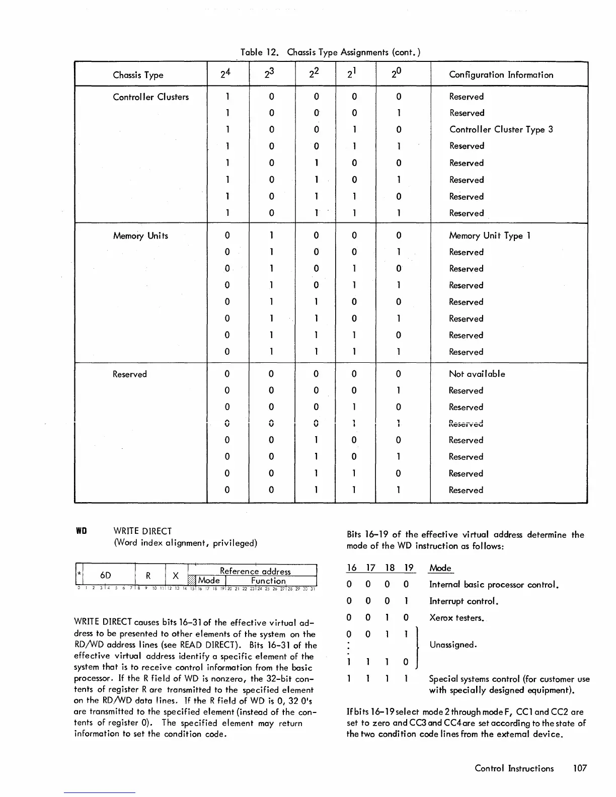
Table 12. Chassis Type Assignments
(cont.)
Chassis Type
24
2
3
22
Control I
er
CI
usters
1
0 0
1 0 0
1
0 0
1
0 0
1
0
1
1
0
1
1
0
1
1
0 1
Memory Units
0
1
0
0
1
0
0
1
0
0
1
0
0
1 1
0
1 1
0
1 1
0
1
1
Reserved
0 0 0
0 0 0
0 0 0
0
1'\
1'\
V V
0 0
1
0 0
1
0 0
1
0 0
1
WD
WRITE
DIRECT
(Word index
alignment,
privileged)
WRITE
DIRECT
causes bits 16-31 of the
effective
virtual
ad-
dress to be presented to
other
elements
of
the system on the
RD/vVD
address I ines (see
READ
DIRECT).
Bits
16-31 of the
effective
virtual address identify a
specific
element
of
the
system
that
is
to
receive
control information from the basic
processor.
If
the R field of
WD
is
nonzero,
the
32-bit
con-
tents of register R
are
transmitted to
the
specified
element
on the
RD/WD
data
lines.
If
the R field of
WD
is
0,
32
O's
are
transmitted to the specified element (instead
of
the
con-
tents of register 0). The specified element may return
information to set the condition code.
21
2
0
Configuration Information
0 0
Reserved
0
1
Reserved
1
0
Controller
Cluster Type 3
1
1
Reserved
0
0
Reserved
0
1 Reserved
1
0
Reserved
1
1 Reserved
0 0 Memory
Uni
t Type 1
0
1
Reserved
1
0
Reserved
1 1
Reserved
0 0 Reserved
0 1 Reserved
1
0 Reserved
1 1
Reserved
0 0
Not
available
0
1
Reserved
1
0
Reserved
, ,
D
______
..1
I I
''l.C;)CIYCU
0
0
Reserved
0
1 Reserved
1
0
Reserved
1
1 Reserved
Bits
16-19
of
the
effective
virtual address determine
the
mode
of
the
WD
instruction as follows:
16 17 18
0
0
0
0 0
0
0
0
0 0
19
0
0
0
}
Mode
Internal basi c processor control.
Interrupt
control.
Xerox testers.
Unassigned.
Special systems control (for customer use
with
specially
designed equipment).
If
bits
16-19select
mode 2 through mode F,
CCl
andCC2
are
set
to
zero
and
CC3 and
CC4are
set according to the
state
of
the two condition
code
lines
from
the
external
device.
Control Instructions 107

 Loading...