Table
15.
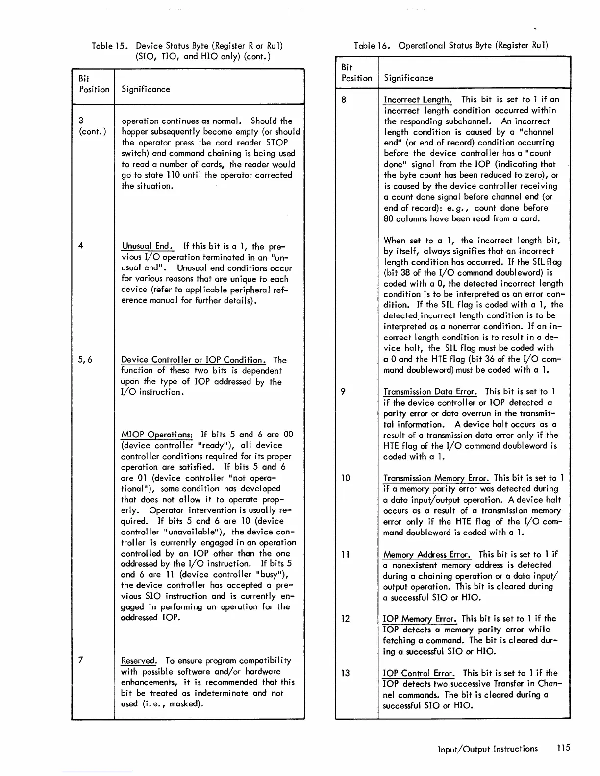
Device Status Byte (Register R or
Ru1)
(SIO, TIO, and HIO only)
(cont.)
Bit
Position Significance
3
(cont. )
4
5,6
7
operation continues as normal. Should
the
hopper subsequently become empty (or should
the
operator press
the
card
reader STOP
switch) and command
chaining
is being used
to
read a number of cards,
the
reader would
go
to state 110 unti I
the
operator
corrected
the
situation.
Unusual End. If this
bit
is
a 1, the
pre-
vious
I/O
operation terminated
in
an "
un
-
usual
end".
Unusual end conditions
occur
for various reasons
that
are
unique to
each
device
(refer to appl
icable
periphera I
ref-
erence
manua I for further
deta
iI
s)
•
Device Controller
or
lOP
Condition.
The
function
of
these two bits
is
dependent
upon
the
type
of
lOP
addressed by the
I/o
instruction.
MIOP Operations:
If
bits 5 and 6
are
00
(device controller
"ready"),
all
device
controller conditions required for its proper
operation
are
satisfied.
If
bits 5 and 6
are
01
(device
controller
"not
opera-
tional"),
some
condition
has developed
that
does not allow
it
to
operate
prop-
erl y .
Operator
i ntervent i on is usua
II
y
re-
quired.
If
bits 5 and 6
are
10
(device
controller
"unavailable"),
the
device
con-
troller is currently engaged in
an
operation
controlled
by
an
lOP
other than
the
one
addressed by
the
I/O
instruction.
If
bits 5
and
6
are
11
(device controller "busy"),
the
device
controller
has
accepted
a
pre-
vious SIO instruction and is currently
en-
gaged
in performing
an
operation for
the
addressed
lOP.
Reserved.
To
ensure program compatibility
with possible software
and/or
hardware
enhancements,
it
is recommended
that
this
bit
be
treated
as
indeterminate and not
used (i.
e.,
masked).
Table
16.
Operational
Status Byte (Register
Ru1)
Bit
Position Significance
8
9
10
11
12
13
Incorrect Length. This bit is set to 1
if
an
incorrect length condition occurred within
the
responding subchannel.
An
incorrect
length condition is caused by a "channel
end" (or end of record) condition occurring
before
the
device
controller has a
"count
done" signal from the
lOP
(indicating
that
the
byte
count
has been reduced
to
zero),
or
is caused by
the
device
controller
receiving
a
count
done signal before channel end (or
end of record):
e.
g.,
count done before
80
columns have been read
from
a
card.
When set to a 1,
the
incorrect length
bit,
by itself, always signifies
that
an
incorrect
length condition has occurred.
If
the
SIL
flag
(bit
38 of the
I/O
command doubleword) is
coded with a
0,
the
detected
incorrect length
condi ti on is to be interpreted as
an
error
con-
dition.
If
the
SIL
flag is coded with a 1,
the
detected.
incorrect
length condition is to be
interpreted as a nonerror condition.
If
an
in-
correct
length condition is to result in a
de-
vice
halt,
the
SIL
flag must be coded with
a 0 and
the
HTE
flag (bit 36 of
the
I/O
com-
mand doubleword) must be coded with a
1.
Transmission Data Error. This bit
is
set to 1
if
the
device
controller or
lOP
detected
a
parity error or
daTa
overrun in
Tne
Transmit-
tal information. A
device
halt
occurs as a
result of a transmission
data
error only if the
HTE
flag of
the
I/o
command doubleword is
coded with a
1.
Transmission Memory Error. This bit is set to 1
if a memory parity error was
detected
during
a
data
input/output
operation. A
device
halt
occurs
as
a result of a transmission memory
error only if the
HTE
flag of
the
I/O
com-
mand doubleword is coded with a
1.
Memory Address Error. This
bit
is set
to
1 if
a nonexistent memory address is
detected
during a
chaining
operation or a
data
input/
output operation. This bit is
cleared
during
a successful
SIO
or HIO.
lOP
Memory Error. This bit is
set
to 1 if the
lOP
detects
a memory parity error while
fetching a command. The bit is
cleared
dur-
ing a successful
SIO
or HIO.
lOP
Control Error. This
bit
is set to 1 if the
lOP
detects
two successive Transfer in
Chan-
nel commands. The bit is
cleared
during a
successful SIO or HIO.
Input/Output
Instructions 115

 Loading...


