2 3 4 Meaning
o 0 0 Not possible.
o 1 0 Parity error
detected
on returned status
and/or
condition
code.
The
result of
the
TDV
is
indeterminate.
1 1 0 0
I/O
address not recognized,
TDV
not
accepted,
and status information returned to
the
general
registers is incorrect.
1 1 1 0 Incoming parity error
detected
by
processor
and
TDV
aborted.
No
status information
re-
turned
to
general registers.
If
CC4 = 1, the MIOP is in
the
test mode and the meaning
of the condition
code
during a
TDV
is:
2 3 4 Meaning
000
o 0
o 0
o 1
o
HID
Unit is performing
an
Order
Out
operation.
Unit is performing
an
Order In operation.
Unit is performing a Data
Out
operation.
Pari ty error
detected
by Processor
Interface
on returned status
and/or
condition
code.
The
result of the
TDV
is indeterminate.
Unit is performing a Data In operation.
nrt:
...I~~",_~""...I
,
..
k.:
I""
11,..:+
norf"'rrn:,..
........
f)
....
fn
Tn
.,"""
............
-'-1'._-
........
- _
....
r-
...
_·
......
v -
-_.-
---
operation.
HALT
INPUT/OUTPUT
0Nord index alignment, t privileged)
HALT
INPUT/OUTPUT causes
the
addressed
device
to
im-
mediately
halt
its current operation (perhaps improperly,
in
the
case
of magnetic
tape
units, when
the
device
is
forced to stop
at
other than an interrecord gap).
If
the
device
is
in
an
interrupt-pending condition, the condition
is
cleared.
.
If
the
R field of
the
HIO instruction
is
0,
the
condition
code
is set, but
no
general registers
are
affected.
t
When
indexing operation
code
4F
instructions (HIO, RIO,
POLP, POLR), the programmer must make
certain
that
the
summation of the contents of
the
index register and the
I/o
address (bits 18-31 of the instruction word) does not
affect
bits 15-17. When indirect addressing is used,
the
contents
of the indirect address location (bits 15, 16, and
17)
must
specify the desired operation
code
extension.
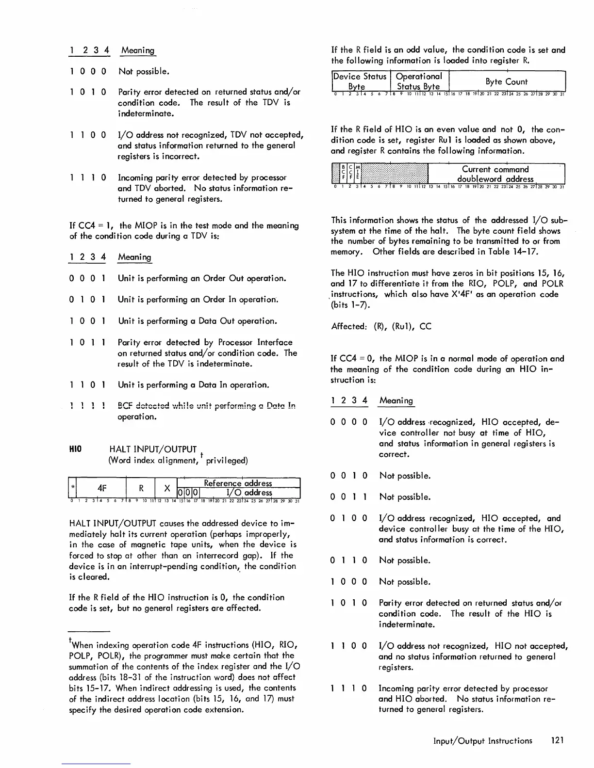
If
the
R field is
an
odd
value,
the condition
code
is set
and
the
following information is loaded into register
R.
If
the
R field of HIO is
an
even
value
and not
0,
the
con-
dition
code
is set, register
Ru1
is loaded as shown
above,
and register R
contains
the following information.
This information shows the status of
the
addressed
I/o
sub-
system
at
the
time of
the
halt.
The
byte
count
field shows
the
number of bytes remaining to be transmitted to or from
memory.
Other
fields
are
described in Table 14-17.
The HIO instruction must have zeros in
bit
positions 15, 16,
and 17 to
differentiate
it
from the RIO, POLP,
and
POLR
,instructions, which also have X
'
4F' as an operation
code
(bits 1-7).
Affected:
(R),
(Ru1), CC
If
CC4 =
0,
the
MIOP
is
in a normal mode of operation
and
the
meaning
of
the
condition
code
during an HIO
in-
structi on is:
2 3 4 Meaning
o 0 0 0
I/o
address .recognized, HIO
accepted,
de-
vice
controller
not busy
at
time of HIO,
and
status information in general registers is
correct.
o 0 0
Not
possible.
o 0
Not
possible.
o 1 0 0
o 0
000
010
I/o
address
recognized,
HIO
accepted,
and
device
controller busy
at
the time of
the
HIO,
and
status information
is
correct.
Not
possible.
Not
possible.
Pari ty error
detected
on returned status
and/or
condition
code.
The result of
the
HIO is
i ndeterm i nate.
1 1 0 0
I/o
address not recognized, HIO not
accepted,
and no status information returned to general
registers.
1 1 1 0 Incoming parity error
detected
by processor
and
HIO aborted. No status information
re-
turned to general registers.
Input/Output
Instructions
121