If
the
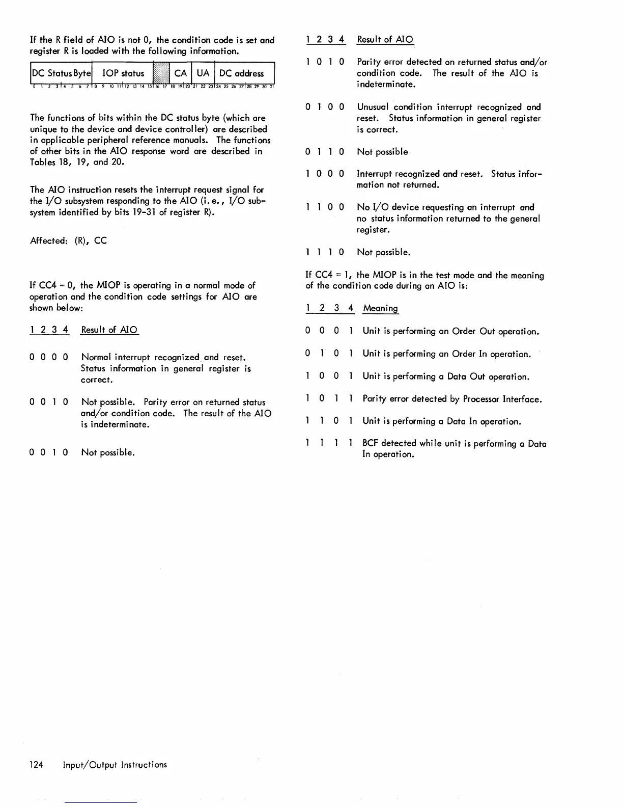
R field of AIO is not
0,
the condition
code
is set and
register R is loaded with
the
following information.
DC
Status Byte
The functions of bits within the
DC
status byte (which
are
unique to
the
device
and
device
controller)
are
described
in
applicable
peripheral reference manuals. The functions
of other bits in
the
AIO response word
are
described in
Tables 18, 19,
and
20.
The
AlO
instruction resets
the
interrupt request signal for
the
I/o
subsystem responding
to
the
AIO
(i.
e.,
I/o
sub-
system
identified
by bits 19-31 of register
R).
Affected: (R), CC
If
CC4 =
0,
the
MIOP
is
operating in a normal mode of
operation and
the
condition
code
settings for AIO
are
shown below:
2 3 4 Result of
AlO
o 0 0 0 Normal interrupt
recognized
and reset.
Status information in general register is
correct.
o 0 1 0
Not
possible. Parity error on returned status
and/or
condition
code.
The result of
the
Ala
is i ndetermi
nate.
o 0 1 0
Not
possible.
124
Input/Output
Instructions
2 3 4 Result of
Ala
o 1 0 Parity error
detected
on returned status
and/or
condition
code.
The result of the AlO is
i ndetermi
nate.
o 1 0 0 Unusual condition interrupt recognized and
reset. Status information in general register
is
correct.
o 1 1 0
Not
possible
1 0 0 0 Interrupt recognized
and
reset. Status infor-
mation not returned.
1 1 0 0
No
I/O
device
requesting an interrupt and
no status i nformati on returned to
the
genera
I
register.
1 1 1 0
Not
possible.
If
CC4 = 1,
the
MIOP is in
the
test mode and the meaning
of the condition
code
during an
Ala
is:
2 3 4 Meaning
0 0 0
Unit is performing
an
Order
Out
operation.
0
0
Unit is performing an
Order
In
operation.
0 0
Unit is performing a Data
Out
operation.
0
Parity error
detected
by Processor Interface.
0
Unit is performing a Data
In
operation.
BCF
detected
whi
Ie unit is performing a Data
In
operation.

 Loading...