Term
IA
II
L
MA
MM
MS
PSWs
R
RA
Ref.
Add.
Meaning
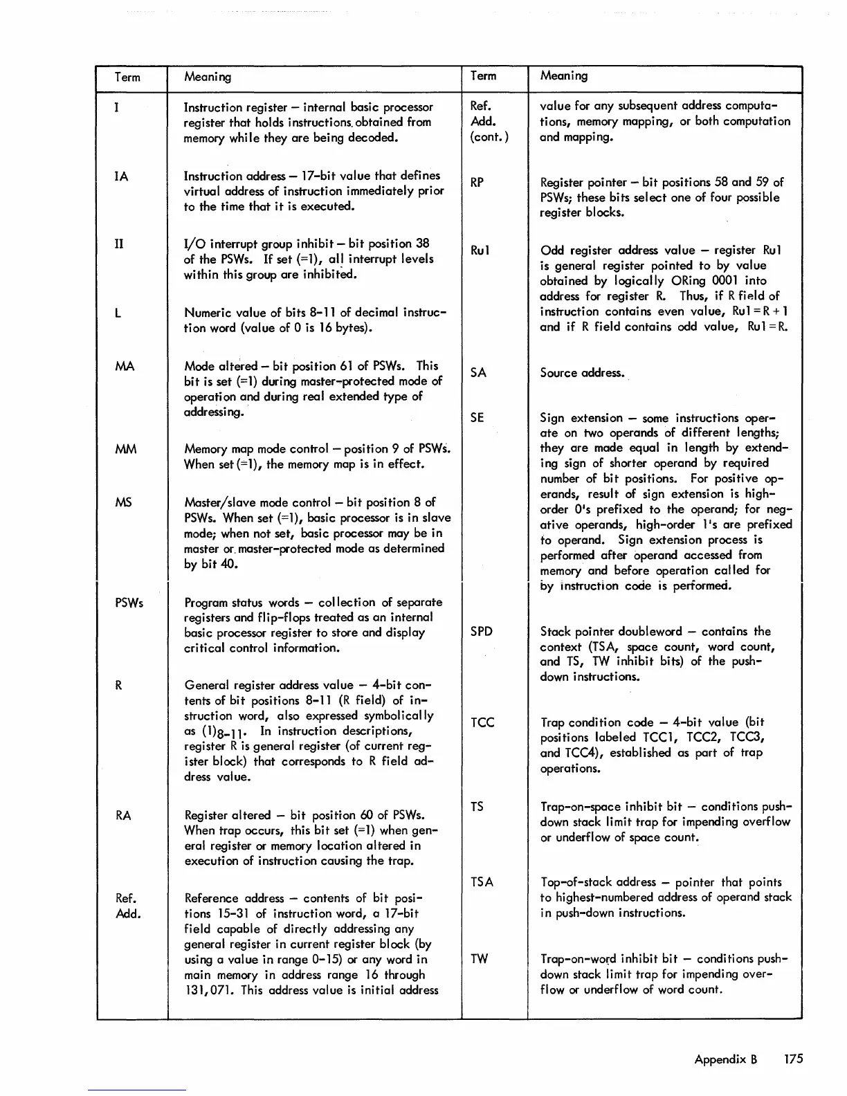
Instruction register - internal basic processor
register
that
holds instructions. obtained
from
memory while they
are
being decoded.
Instruction address - 17-bit value
that
defines
virtual address of instruction immediately prior
to the time
that
it
is executed.
I/O
interrupt group inhibit -
bit
position 38
of the
PSWs.
If
set (=1),
all
interrupt levels
within this group
are
inhibitect.
Numeric value of bits 8-11 of decimal instruc-
tion
word (value of 0 is
16
bytes).
Mode
altered - bit position
61
of
PSWs.
This
bit
is set
(=1)
during master-protected mode of
operati
on
and duri
ng
rea I extended type of
addressing.
Memory map mode control - position 9 of
PSWs.
When set
(==
1), the memory map is in effec t.
Master/slave mode control - bit position 8 of
PSWs.
When set (=1), basic processor
is
in slave
mode; when not
set,
basic processor
may
be in
master
or.
master-protected mode as determined
by bit
40.
Program status words -
collection
of separate
registers and
flip-flops treated as an internal
basic processor register
to
store and display
critical
control information.
General register address value -
4-bit
con-
tents of bit positions 8-11
(R
field) of
in-
struction word, also expressed symbolically
as (1)8-11.
In
instruction descriptions,
register R
is
general register (of current
reg-
ister block) that corresponds to R field
ad-
dress value.
Register altered - bit
position
60
of
PSWs.
When trap occurs, this bit set
(=1)
when
gen-
eral register or memory location
altered
in
executi
on
of i nstructi on causi
ng
the
trap.
Reference address - contents of
bi
t posi-
tions 15-31 of instruction word, a 17-bit
Field
capable
of directly addressing any
general register in current register block (by
using a value in range 0-15) or any word in
ma
in
memory
in address range 16 through
131,071.
This
address value
is
initial address
Term
Ref.
Add.
(cont. )
RP
Rul
SA
SE
SPD
TCC
TS
TSA
TW
Meaning
value
for any subsequent address computa-
tions, memory mapping, or both computation
and mappi ng.
Register pointer -
bit
positions 58 and 59 of
PSWs;
these bits
select
one of four possible
register blocks.
Odd register address
value
- register
Ru1
is general register pointed
to
by value
obtained by
logically ORing 0001 into
address for register
R.
Thus, if R fip.ld of
instruction contains even
value,
Rul
= R + 1
and if R field contains odd
value,
Rul
=
R.
Source address.
Sign extension - some instructions
oper-
ate
on two operands of different lengths;
they
are
made equal in length by
extend-
ing sign of shorter operand by required
number of
bit
positions. For positive
op-
erands, result of sign extension is high-
order
O·s
prefixed to
the
operand; for
neg-
ative
operands, high-order ]Is
are
prefixed
to operand. Sign extension process is
performed
after
operand accessed
from
memory and before operation
called
for
by
Instruction code is performed.
Stack pointer doubleword - contains the
context
(TSA,
space
count,
word count,
and
IS,
TW
inhibit bits) of the push-
down instruct ions.
Trap condition
code
-
4-bit
value (bit
positions labeled
TCC1, TCC2, TCC3,
and TCC4), established as part of trap
operati ons.
Trap-on-space inhibit
bit
- conditions push-
down stack limit
trap
for impending overflow
or underflow of space count.
Top-oF-stack address - pointer that points
to
highest-numbered address of operand stack
i n push-down instructions.
Trap-on-wo{d inhibit
bit
- conditions push-
down stack limit trap
For
impending over-
flow
or
underFlow of word count.
Appendjx B 175