MEMORY MAPPING AND ACCESS PROTECTION
The memory map is
physically
an
array
of
256
l1-bit
reg-
isters. The
array
resides in
the
Memory
Interface
(MI)
of
the
processor
cluster
containing
the
basic
processor. Each
register has
an
8-bit
address
(that
corresponds
to
an
8-bit
virtual
page
address) and
contains
an
ll-bit
actual
page
address for a
specific
512-word
page
of
memory. Mapping
always transforms a
17-bitvirtual
address
into
a
20-bit
real
address.
The
actual
page
addresses
are
assigned to pages
of
virtual
addresses in this manner:
Actual
page
X
(11
bits)
Actual
page
K
(11
bits)
Vi
rtua I addresses
Vi
rtua I addresses
X
'
lO'-X'l
FF' X
'200'-X
'
3FF'
(virtual
page
0) (virtual
page
1)
Ac tua I
page
N
(11
bits)
Virtual addresses
XI
1 F
EOO
1-
XI
1 F F F F 1
(virtual
page
255)
Just
prior to a memory
reference,
the
most
significant
8 bits
of
a
17-bit
virtual
address
are
used as the address
of
an
element
of
the
map
array.
The
11
bits
contained
within
that
element
are
then used in
conjunction
with
the
low-
order
9 bits
of
the
17-bit
virtual address to produce a
20-bit
actua
I
address.
Sigma
6/7
compatible
mapping
is
accomplished
by
loading
the
map with
8-bit
address elements (instead
of
11-bit
ad-
dress elements) via
the
MOVE TO MEMORY
CONTROL
(MMC)
instruction.
The 8 bits
are
stored in
the
low-order
8 bits
of
each
map
element
and the 3
high-order
bit
posi-
tions
are
reset
to
zero.
Thus
the
map will
always
relocate
to
the
same address in the first 128K words
of
real memory
and
be
compatible
for Sigma
6/7
programs.
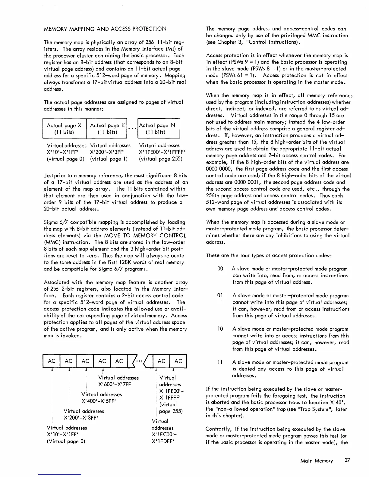
Associated with
the
memory map
feature
is
another
array
of
256
2-bit
registers, also
located
in
the
Memory
Inter-
face.
Each
register
contains
a
2-bit
access
control
code
for a
specific
512-word
page
of
virtual addresses. The
access-protection
code
indicates
the
allowed
use or
avail-
ability
of
the
corresponding
page
of
virtual
memory. Access
protection
applies
to
all
pages
of
the
virtual address
space
of
the
active
program, and is only
active
when
the
memory
map
is
invoked.
Vi
rtual addresses
X'600
'
-X'7FF'
Virtual addresses
X'400'-X
'
5FF'
Virtual addresses
X'200'-X'3FF'
Virtual addresses
X'10'-X'lFF'
(Virtual
page
0)
Virtual
addresses
X'lFEOO'-
X'l
FFFF'
(virtual
page
255)
Virtual
addresses
X'lFCOO'-
X'lFDFF'
The memory
page
address
and
access-control
codes
can
be
changed
only by use of
the
privileged
MMC instruction
(see
Chapter
3,
"Control Instructions).
Access
protection
is
in
effect
whenever
the
memory map
is
in
effect
(PSWs 9 =
1)
and
the
basic
processor
is
operating
in
the
slave
mode
(PSWs
8 =
1)
or
in
the
master-protected
mode (PSWs61
=1).
Access
protection
is
not
in
effect
when
the
basic
processor
is
operating
in the master
mode.
When
the
memory map is in
effect,
all
memory
references
used by
the
program (including instruction addresses)
whether
direct,
indirect,
or
indexed,
are
referred
to
as
virtual
ad-
dresses. Virtual addresses in
the
range 0 through
15
are
not used
to
address main memory; instead
the
4
low-order
bits
of
the
virtual
address comprise a
general
register
ad-
dress. If,
however,
an
instruction produces a virtual
ad-
dress
greater
than 15,
the
8
high-order
bits
of
the
virtual
address
are
used
to
obtain
the
appropriate
l1-bit
actual
memory
page
address and
2-bit
access
control
codes.
For
example,
if
the
8
high-order
bits
of
the
virtual
address
are
0000
0000,
the
first
page
address
code
and
the
first
access
control
code
are
used;
if
the
8
high-order
bits
of
the
virtual
address
are
0000 0001,
the
second
page
address
code
and
the
second
access
control
code
are
used,
etc.,
through
the
256th
page
address and
access
control
codes.
Thus
each
512-word
page
of
virtual addresses is
associated
with its
own memory
page
address
and
access
control
codes.
When
the
memory map
is
accessed
during a
slave
mode
or
master-protected
mode program,
the
basic processor
deter-
mines
whether
there
are
any inhibitions to using
the
virtual
address.
These
are
the
four types of
access
protection
codes:
00 A
slave
mode or
master-protected
mode program
can
write
into,
read from, or
access
instructions
from this
page
of
virtual address.
01
A
slave
mode or
master-protected
mode program
cannot
write
into this
page
of
virtual addresses;
it
can,
however, read
from
or
access
instructions
from this
page
of
virtual
addresses.
10
A
slave
mode or
master-protected
mode program
cannot
write
into or
access
instructions
from
this
page
of
virtual addresses;
it
can,
however,
read
from this
page
of
virtual addresses.
11
A
slave
mode or
master-protected
mode program
is
denied
any
access
to this
page
of
virtua I
addresses.
If
the
instruction
being
executed
by the
slave
or
master-
protected
program fai
Is
the foregoing
test,
the
instruction
is
aborted
and
the
basic processor traps
to
location
X
'40
1
,
the
"non-allowed
operation"
trap (see "Trap System",
later
in this
chapter).
Contrarily,
if
the
instruction
being
executed
by
the
slave
mode
or
master-protected
mode program passes this test (or
if
the
basic
processor
is
operating
in
the
master mode),
the
Main Memory 27