General Procedures and Information
PHASER 3124 / PHASER 3125 09/06 6-19
• Supply
Output Voltage : -550 V ± 8.6%(ZENER using, DEV )
Input contrast of the output stability degree : under ± 5%
Loading contrast : ± 5% or less
Output Voltage Rising Time : 50 ms Max
Output Voltage Falling Time : 50 ms Max
Output Loading range : 10 ~ 1000
Output Control Signal (BIAS-PWM) : the CPU is HV output when PWM is low.
• Input
Fuser AC Power Control
Fuser (HEAT LAMP) gets heat from AC power. The AV power controls the switch with the Triac,
a semiconductor switch. The 'ON/OFF control' is operated when the gate of the Triac is turned on/
off by Phototriac (insulting part).In other words, the AC control part is passive circuit, so it turns
the heater on/off with taking signal from engine control part.
When the 'HEATER ON' signal is turned on at engine, the LED of PC1 (Photo Triac) takes the
voltage and flashes. From the flashing light, the triac part (light receiving part) takes the voltage,
and the voltage is supplied to the gate of triac and flows into the triac. As a result, the AC current
flows in the heat lamp, and heat is occurred.
On the other hand, when the signal is off, the PC1 is off, the voltage is cut off at the gate of triac,
the triac turns off, and then the heat lamp is turned off.
• Triac (THY1) feature :16A, 600V SWITCHING
• Phototriac coupler (PC3)
Turn ON if current : 16mA
High repetive peak off state voltage : Min 600V
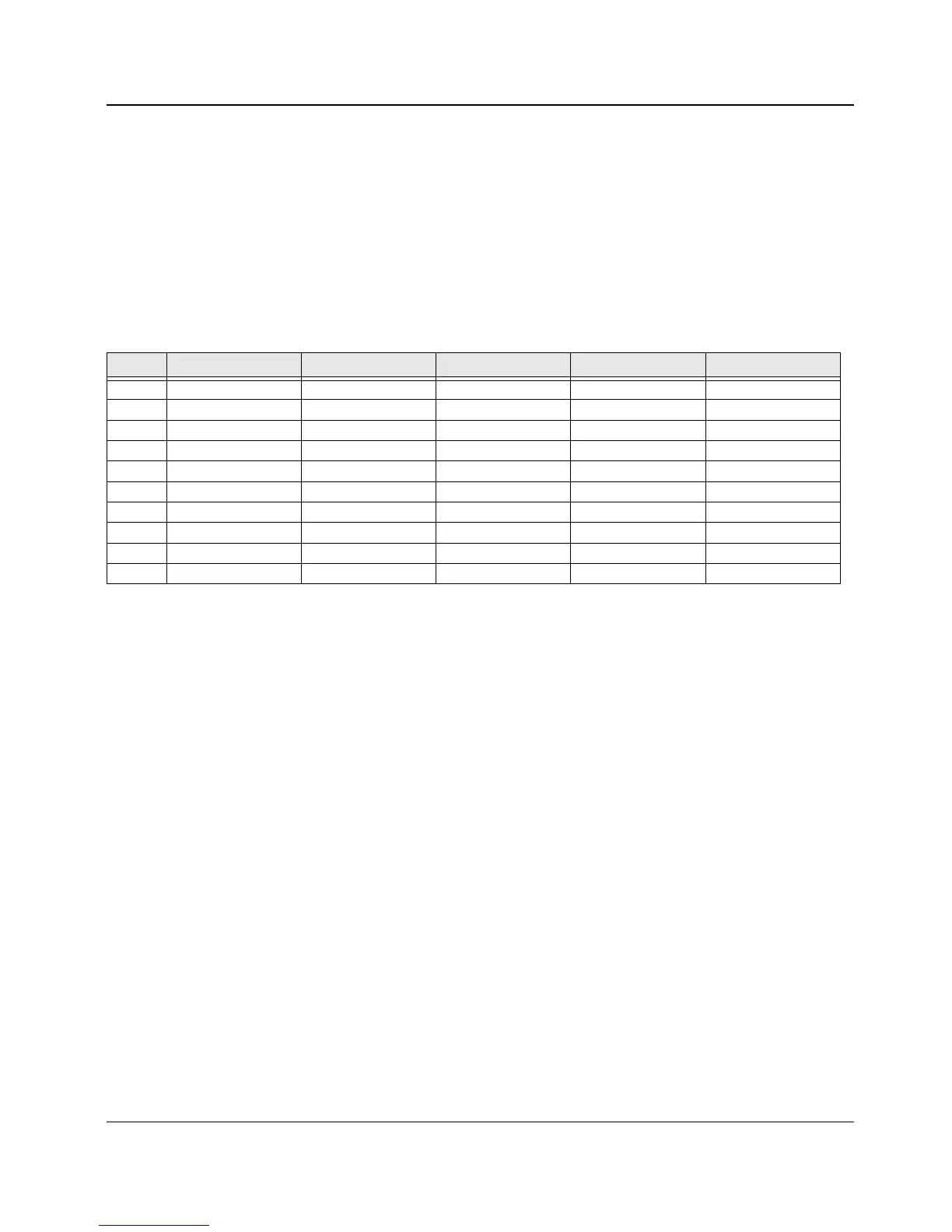
Table 2: Input
Pin NO Signal Name Remark Pin NO Signal Name Remark
1+24VS 11 MHVPWM
2 +24VS 12 THVREAD
3 +24VS2 13 BIAS-PWM
4+24VS2 14 FAN
5+24VS2 15 P_EMPTY
6 +3.3 16 CRU_DET
7DGND 17 KEY_IN
8 P_EXIT 18 TONERSAVE
9 THV_PWM 19 ERROR
10 THVEN 20 READY

 Loading...