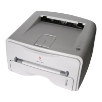
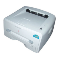
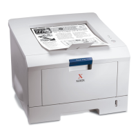
General Procedures and Information
6-18 09/06 PHASER 3124 / PHASER 3125
HVPS
The HVPS creates the high voltage of THV/MHV/Supply/Dev and supplies it to the developer part
for making best condition to display the image. The HVPS part takes the 24V and outputs the high
voltage for THV/MHV/BIAS, and the output high voltage is supplied to the toner, OPC cartridge,
and transfer roller.
• Transfer High Voltage (THV+)
Input Voltage : 24 V DC ° ± 15%
Out Voltage : Max. +1.3KV ° ± 15% (Cleaning,200 Mega Ohms )
Out Voltage Trigger : 6.5µA
Input Voltage Variation : ± 5% below (Variation 21.6V~ 26.4V)
Out Voltage Rising Time : 100 ms Max
Out Voltage Falling Time : 100 ms Max
Transfer Variation Voltage on Environment Variation : +650 V (Duty 10%) ~ 5KV (Duty
90%)
Control method on environment : THV-PWM ACTIVE, transfer active signal, of environ-
ment sensing voltage is input and get feedback current, and recalculate it to resistance.
Control method on transfer output voltage : It is controlled by changing its duty of
THVPWM signal as follows. 10% Duty : +650V, 90% Duty : +5KV ± 5%
• Charge Voltage (MHV)
Input Voltage : 24 V DC ± 15%
Out Voltage : -1.3KV ~ ± 3.2%
Out Voltage Rising Time : 50 ms Max
Out Voltage Falling Time : 50 ms Max
Out Voltage Range : 30MΩ ~ 1000MΩ
Output Control Signal (MHV-PWM) : CPU is HV output when PWM is low
• Developing Voltage (DEV)
Input Voltage : 24 V DC ± 15%
Output Voltage: -350V ± 4.6%
Output Voltage fluctuation range: PWM Control
Input contrast of the output stability degree : ±5 % or less
Loading contrast : ±5 % or less
Output Voltage Rising Time : 50 ms Max
Output Voltage Falling Time : 50 ms Max
Output Loading range : 10Mߟ ~ 1000
Output Control Signal (BIAS-PWM) : the CPU output is HV output when PWM is low.

 Loading...