Embedded Tri-Mode Ethernet MAC User Guide www.xilinx.com 81
UG074 (v2.2) February 22, 2010
Host Interface
R
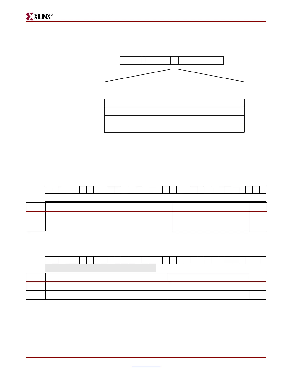
Figure 3-42 shows the multicast address table memory diagram.
The five address filter registers and the contents of the registers are shown in Table 3-16
through Table 3-20.
Figure 3-42: Multicast Address Table Memory Diagram.
Multicast Address Register 2
Multicast Address Register 0
47 0
00
01
10
11
Multicast Address Register 1
Multicast Address Table
Multicast Address Table Access (Word 1)
HOST_ADDR
31 0
MULTICAST_ADDRESS[47:32]
Multicast Address Register 3
ADDR
16 151723
LSB
MSB
MSB
LSB
ADDR
RNW
0x38C/0x78C
ug074_3_44_080805
Table 3-16: Unicast Address (Word 0)
MSB
LSB
313029282726252423222120191817161514131211109876543210
0x380 UNICAST_ADDRESS[31:0]
Bit Description Default Value R/W
[31:0]
Unicast Address [31:0]. This address is used to match the
Ethernet MAC against the destination address of any
incoming frames.
TIEEMAC#UNICASTADDR[31:0] R/W
Table 3-17: Unicast Address (Word 1)
MSB
LSB
313029282726252423222120191817161514131211109876543210
0x384
RESERVED UNICAST_ADDRESS[47:32]
Bit Description Default Value R/W
[15:0] Unicast Address [47:32]. TIEEMAC#UNICASTADDR[47:32] R/W
[31:16] Reserved. –