Chapter Three - Installation
27
Power Panel
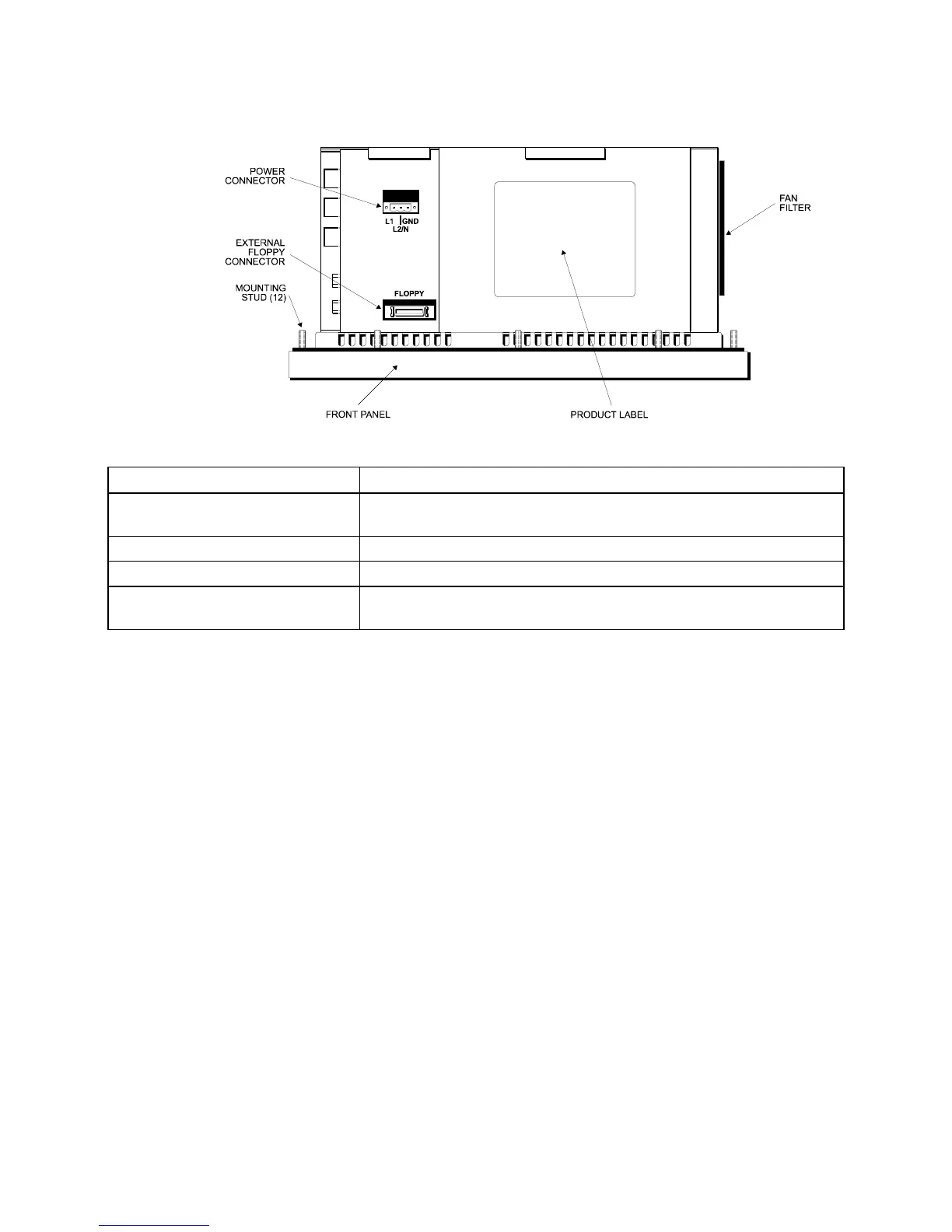
Figure 3-7. Bottom Panel with Power Connector and External Floppy Connector
Feature Description
Power Connector This is a three-pin connector. Refer to the special hazardous
location installation instructions later in this chapter.
External Floppy Drive Connector This is a 26-pin connector.
Product ID Label The product ID label is located on the bottom panel
Fan and Filter The filter can be replaced or removed for cleaning. See Chapter 5
for details on the fan filter assembly.
Preparing the System
Read this chapter first, comply with all the safety requirements, and then mount the
unit according to the following instructions.
1. Locate a position that meets the required specifications.
2. Create a panel cutout. The dimensions are given in this chapter.
3. Install optional equipment following the instructions in Installing Internal
Hardware Options and Installing External Hardware Options in this chapter.
4. Create a power cable. Refer to the Creating a Power Cable section in this
chapter.
5. Mount the system and properly secure the unit into the panel. See Installing the
System section in this chapter.
6. Attach one end of the power cord to the power receptacle and the other end to a
properly grounded 115/230 VAC, 50-60 Hz outlet or a 24 VDC outlet,
whichever applies (refer to the Hazardous Location Installations section later in
this chapter).
7. Turn on power to the system. The system will boot up to the operating system
installed.
8. Install the application software via a floppy drive.