3500 Flat Panel Industrial PCs
54
5. Attach the power cable making sure that the system’s enclosure is grounded
through the power cable.
6. Implement the proper grounding techniques. Establish a ground path from the
unit chassis to the enclosure chassis. A 6-32 threaded ground point hole is
provided on the bottom panel of the unit.
7. Tighten the 12-#10 nuts to 25 lbs-inch (2.8 Newton-meters) (28Kgf cm).
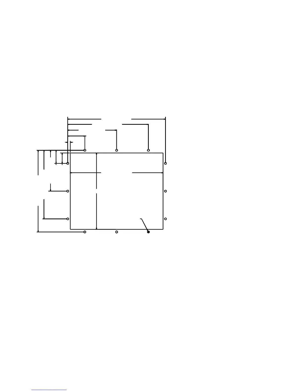
System Cutout Dimensions
3510(T)/3512(T)
1.315 [33.40]
.315 [8.00]
2.150 [54.61]
6.150 [156.21]
10.150 [257.81]
12.300 [312.42]
1.650 [41.91]
5.150 [130.81]
8.650 [219.71]
10.300 [2
1.
2]
11.670 [296.42]
9.630 [244.60]
ø.250 [ø6.35]
Figure 3-23. 3510/3512 System Cutout Dimensions (inches [mm])