5-12
E
POWR
STATOR AND TIMING BELT
STATOR AND TIMING BELT
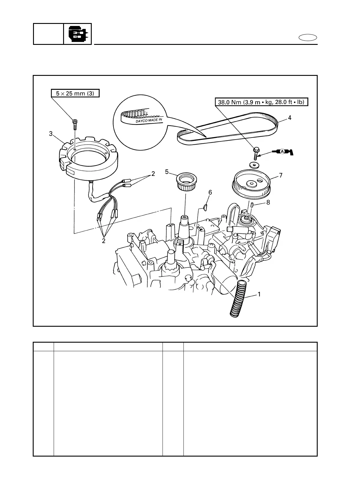
EXPLODED DIAGRAM
REMOVAL AND INSTALLATION CHART
Step Procedure/Part name Q’ty Service points
STATOR AND TIMING BELT
REMOVAL
Follow the left “Step” for removal.
Flywheel magneto Refer to “FLYWHEEL MAGNETO”.
1 Corregated plastic sheave 1
2 Stator lead 6
3 Stator 1
4 Timing belt 1
5 Drive sprocket 1
6 Woodruff key 1
7 Driven sprocket 1
8 Dowel pin 1
Reverse the removal steps for installation.