4-1
E
FUEL
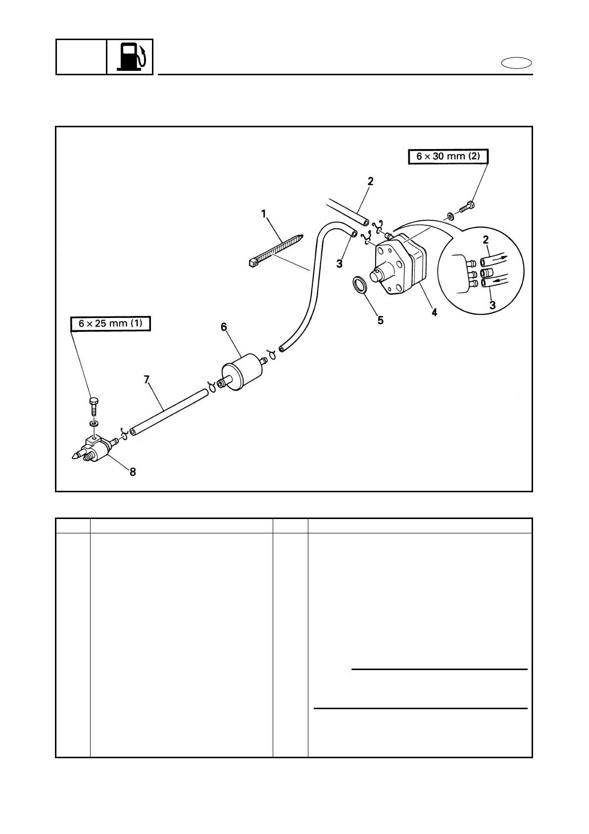
FUEL JOINT, FUEL FILTER, AND FUEL PUMP
FUEL JOINT, FUEL FILTER, AND FUEL PUMP
EXPLODED DIAGRAM
REMOVAL AND INSTALLATION CHART
Step Procedure/Part name Q’ty Service points
FUEL JOINT, FUEL FILTER AND
FUEL PUMP REMOVAL
Follow the left “Step” for removal.
1 Plastic locking tie 1 With the oil pan breather hose.
2 Fuel hose
(fuel pump-to-carburetor)
1
3 Fuel hose
(fuel filter-to-fuel pump)
1
4 Fuel pump 1
5 O-ring 1
6 Fuel filter 1
7 Fuel hose (fuel joint-to-fuel filter) 1
8 Fuel joint 1
Reverse the removal steps for installation.
NOTE:
The flange side of the fuel filter must face
towards the fuel joint.