5-1
E
POWR
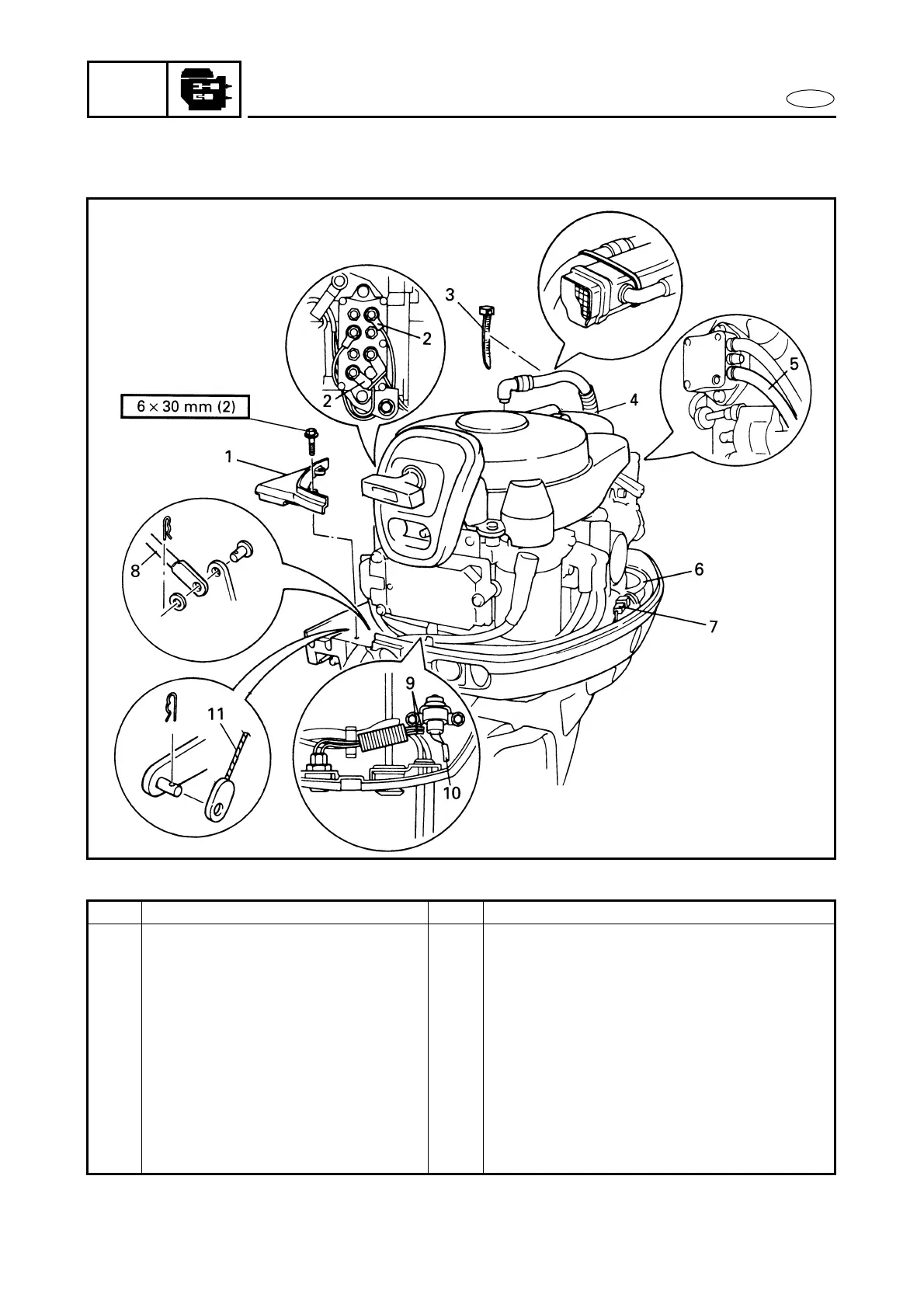
POWER UNIT
EXPLODED DIAGRAM
REMOVAL AND INSTALLATION CHART
Step Procedure/Part name Q’ty Service points
POWER UNIT REMOVAL
Follow the left “Step” for removal.
Battery cables (at the battery)
Throttle cables (MH, EH, EHT)
Engine stop switch leads
(MH, EH, EHT)
Low-oil-pressure warning lamp
leads
Refer to “FLYWHEEL MAGNETO”.
1 Fitting plate 1
2 PTT motor lead (EHT, ET) 2 Blue, Green
3 Plastic locking tie 1
4 Oil pan breather hose 1
POWER UNIT