5-7
E
POWR
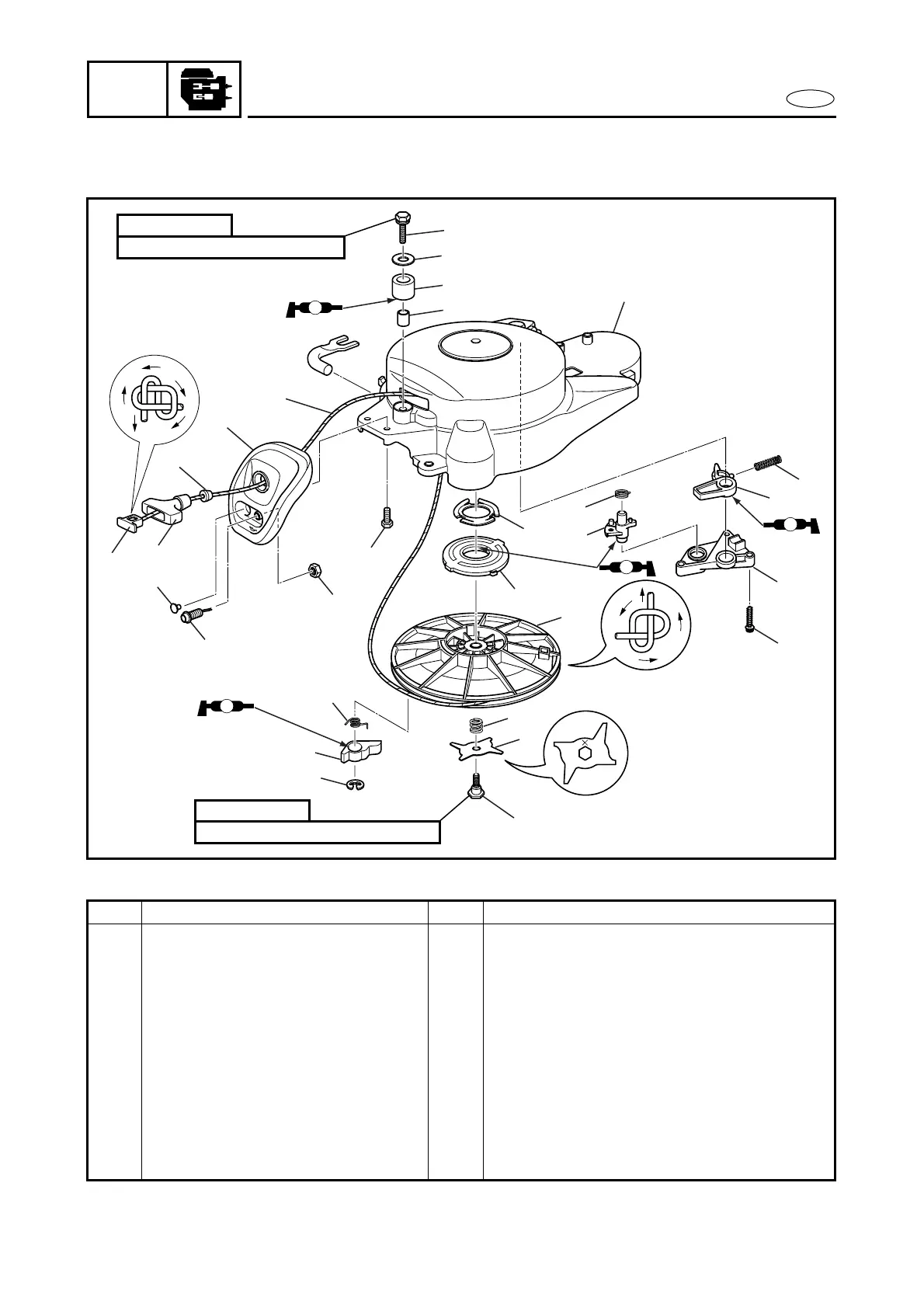
RECOIL STARTER
RECOIL STARTER
EXPLODED DIAGRAM
25
26
28
27
21
20
6
7
4
5 3
2
2
1
24
23
22
14
15
17
16
18
19
12
13
10
11
9
8
A
A
A
A
6 × 30 mm
8.0 Nm (0.8 m
• kg, 5.9 ft • Ib)
6 × 25 mm
15.0 Nm (1.5 m
• kg, 11.1 ft • Ib)
REMOVAL AND INSTALLATION CHART
Step Procedure/Part name Q’ty Service points
RECOIL STARTER DISASSEMBLY
Follow the left “Step” for removal.
1 Cap 1
2 Low-oil-pressure warning lamp 1
3 Bolt 2
4 Starter-handle end-piece 1
5 Starter handle 1
6 Damper 1
7 Starter rope guide 1
8 Bolt 3
9 Lock cam retainer 1
10 Spring 1