CHASSIS
3-30
EAS1SM1104
CHECKING THE SWINGARM OPERATION
1. Check:
• Swingarm smooth action
• Swingarm free play
Refer to “SWINGARM” on page 4-60.
EAS1SM1105
CHECKING THE REAR SUSPENSION
1. Stand the vehicle upright on a level surface.
EWA@
Securely support the vehicle so that there is
no danger of it falling over.
2. Check:
• Rear shock absorber assembly
Gas leaks/oil leaks Replace the rear
shock absorber assembly.
Refer to “REAR SHOCK ABSORBER AS-
SEMBLY” on page 4-53.
3. Check:
• Rear shock absorber assembly smooth ac-
tion
• Rear suspension link smooth action
Sit astride the seat and shake your body up
and down several times to check whether
the rear shock absorber assembly operates
smoothly.
Unsmooth operation Correct or replace.
Refer to “REAR SHOCK ABSORBER AS-
SEMBLY” on page 4-53.
EAS1SM1106
ADJUSTING THE REAR SHOCK ABSORB-
ER ASSEMBLY
Use a suitable stand to raise the rear wheel off
the ground.
EWA13120
Securely support the vehicle so that there is
no danger of it falling over.
Spring preload
ECA13590
Do not turn the adjuster forcibly beyond its
adjusting range.
1. Remove:
• Rear frame
Refer to “REAR SHOCK ABSORBER AS-
SEMBLY” on page 4-53.
2. Adjust:
• Spring preload
▼▼▼▼▼▼▼▼▼▼▼▼▼▼▼▼▼▼▼▼▼▼▼▼▼▼▼▼▼▼▼▼
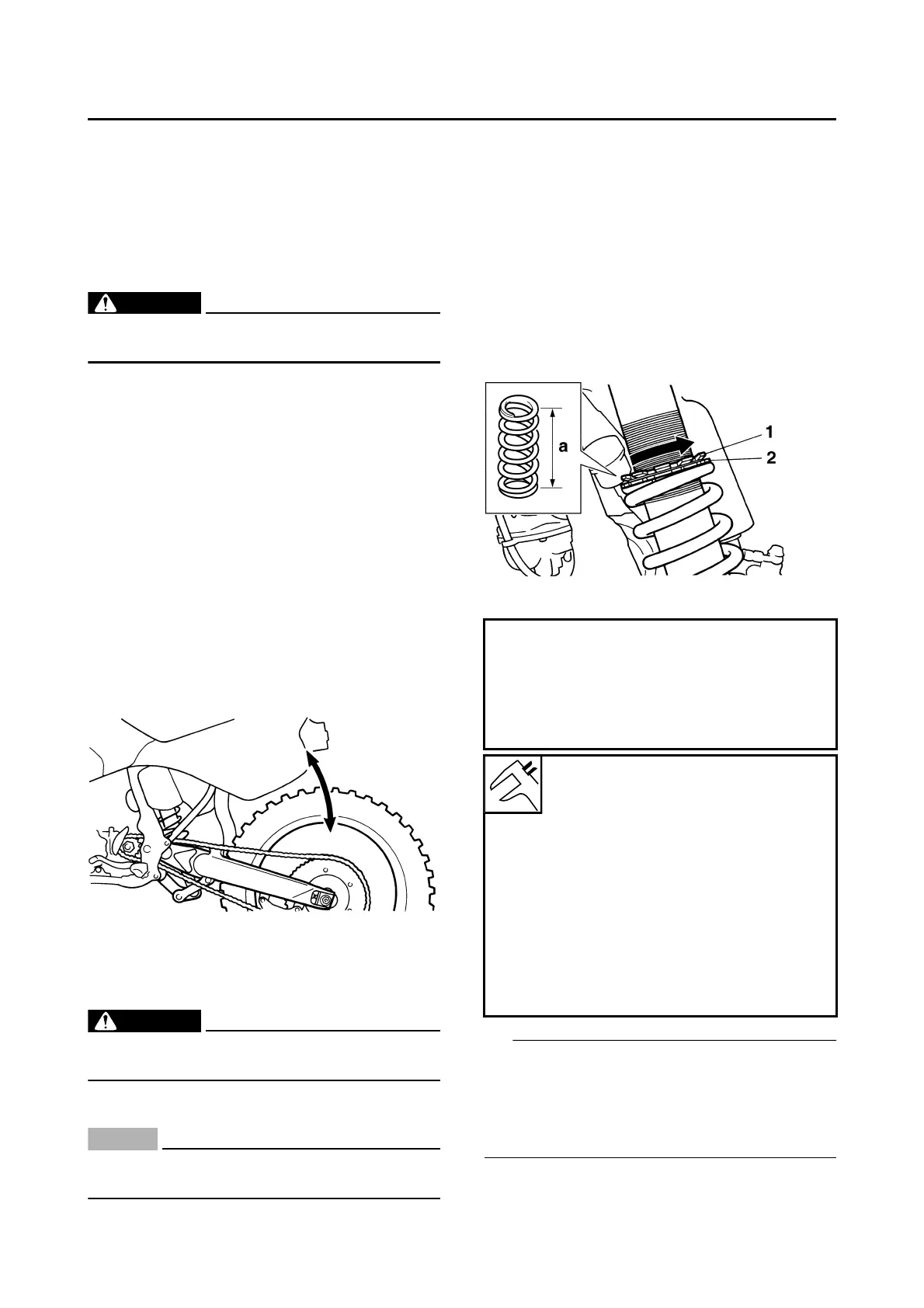
a. Loosen the locknut “1”.
b. Loosen the adjuster “2” until there is some
clearance between the spring and the ad-
juster.
c. Measure the spring free length “a”.
d. Turn the adjuster in the direction of “b” or “c”
to make an adjustment.
• Be sure to remove all dirt and mud from
around the locknut and adjusting ring before
adjustment.
• The length of the spring (installed) changes
1.5 mm (0.06 in) per turn of the adjusting ring.
Direction “b”
Spring preload is increased (suspen-
sion is harder).
Direction “c”
Spring preload is decreased (suspen-
sion is softer).
Spring installed length “d”
Minimum
Position in which the spring is
turned in 1.5 mm (0.06 in) from
its free length.
STD
Position in which the spring is
turned in 10 mm (0.39 in) from its
free length.
Maximum
Position in which the spring is
turned in 18 mm (0.71 in) from its
free length.