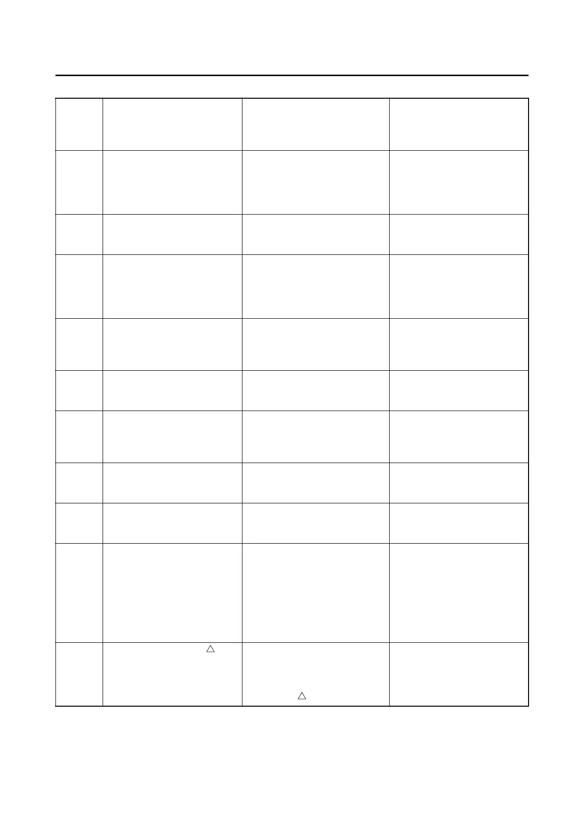
LIST OF SELF-DIAGNOSTIC AND FAIL-SAFE ACTIONS
9-5
SENSOR OPERATION TABLE
Diag-
nostic
code
No.
ITEM Display Procedure
01 Throttle angle
• Fully closed position
• Fully opened position
Displays the throttle angle.
• 11–14
• 109–116
• Check with throttle fully
closed.
• Check with throttle fully
opened.
03 Pressure of suction pipe Displays the intake air pres-
sure.
The atmospheric pressure
is displayed on the Yamaha
diagnostic tool.
05 Intake air temperature Displays the intake air tem-
perature.
Compare the actually mea-
sured intake air tempera-
ture with the Yamaha
diagnostic tool display val-
ue.
06 Coolant temperature Displays the coolant temper-
ature.
Compare the actually mea-
sured coolant temperature
with the Yamaha diagnostic
tool display value.
08 Lean angle sensor
• Upright
•Overturn
Displays the output voltage.
• 1.0 (V)
• 4.0 (V)
Remove the ECU, and in-
cline it 45 ° or more.
09 Monitor voltage Displays the voltage of the
external battery connected to
the Yamaha diagnostic tool.
• Approximately 12.0 (V)
—
21 Neutral switch
• Gear in neutral
• Gear not in neutral
•ON
•OFF
Operate the shift pedal.
25 Gear position sensor
• Gear in 1st or 2nd
• Gear not in 1st or 2nd
•ON
•OFF
Operate the shift pedal.
60 EEPROM fault code No.
display
• No fault
• CO adjustment valve
• Power Tuner injection cor-
rection setting 0–8, or
Power Tuner ignition tim-
ing correction setting 0–8
•00
•01
•07
—
61 Malfunction history ( )
code No. display
*
1
• There is no history.
• There is some history.
•00
• Other: Displays the fault
code of ( ).
—




 To Next Page