1 - 6
System Configuration for Analog Output (4 - 20 mA DC output)
continued
System configura-
tion WITHOUT the
communication
function
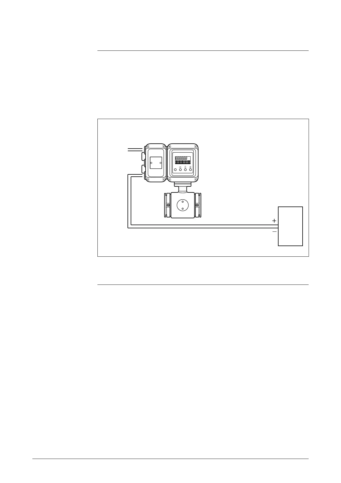
Figure 1-3 shows a sample system configuration in which the instantaneous
flow rate measured by the unit is output with a 4 - 20 mA DC analog signal.
In this system, the DC power supply that transmits the analog signal is inte-
grated into the unit, which can output the analog signal directly to the host
control system.
Figure 1-3 System configuration of analog output WITHOUT communica-
tion function
Host
control
system
AC or DC
power
supply
• Smart Electromagnetic Flowmeter (device): Measures flow rate and out-
puts an analog signal instantaneous flow rate.
Continued on next page
Device


 To Next Page