Network Communications
6
6.3 MEMOBUS/Modbus Communications
YASKAWA SIEPC71061753C GA500 Technical Manual 219
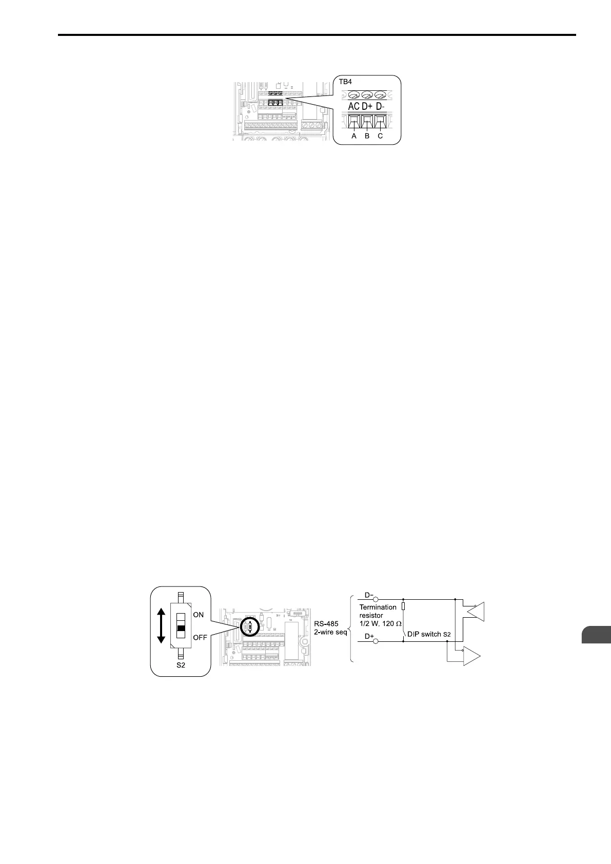
1. De-energize the drive then connect the communications cable to the PLC and the drive. The drive uses
terminal TB4 for MEMOBUS/Modbus communications.
A - Terminal AC: Common ground
B - Terminal D+: Communication input/output (+)
C - Terminal D-: Communication input/output (-)
Figure 6.2 Communications Cable Connection Terminal (TB4)
Note:
Isolate the communications wiring from the main circuit wiring and other high-power wiring Use shielded wires for the
communications wiring and connect cable sheaths to the ground terminal of the drive. Incorrect wiring procedures could
cause drive malfunction because of electrical interference.
2. Install the termination resistor on the network termination slave drive. Set DIP switch S2 to the ON position
to enable the termination resistor on the drive.
3. Energize the drive.
4. Use the drive keypad to set the necessary communications parameters H5-01 to H5-12.
• H5-01 [Drive Node Address]
• H5-02 [Communication Speed Selection]
• H5-03 [Communication Parity Selection]
• H5-04 [Communication Error Stop Method]
• H5-05 [Comm Fault Detection Selection]
• H5-06 [Drive Transmit Wait Time]
• H5-09 [CE Detection Time]
• H5-10 [Modbus Register 0025H Unit Sel]
• H5-11 [Comm ENTER Command Mode]
• H5-12 [Run Command Method Selection]
5. De-energize the drive and wait for the keypad display to turn off.
6. Energize the drive.
The drive is prepared to start communication with the PLC.
■ Set the Termination Resistor
You must enable the termination resistor on the slave terminal of the drive to use MEMOBUS/Modbus
communications. Use DIP switch S2 on the terminal block to enable and disable the built-in termination resistor.
Refer to Figure 6.3 for an example of how to set DIP switch S2. Use the tip of a tweezers or a jig with a tip width
of 0.8 mm (0.03 in) to set the DIP switch. When you install the drive at the end of the communication line, set
DIP switch S2 to ON. Set DIP switch S2 to OFF on all other drives.
Figure 6.3 MEMOBUS/Modbus Communication Terminal and DIP Switch S2
■ Wiring Diagram for More than One Drive
Figure 6.4 shows the correct wiring when you use more than one drive with MEMOBUS/Modbus
communications.
 Loading...


