6.3 MEMOBUS/Modbus Communications
224 YASKAWA SIEPC71061753C GA500 Technical Manual
Byte Command Message
Setting Data
(Hex.)
Response Message (Normal)
Setting Data
(Hex.)
Response Message (Fault)
Setting Data
(Hex.)
2
Starting No.
Upper 00 Data Qty 08 Error code 03
3 Lower 20
First storage
register
Upper 00
CRC-16
Upper F1
4
Data Qty
Upper 00 Lower 65 Lower 31
5 Lower 04
Next storage
register
Upper 00 -
6
CRC-16
Upper 45 Lower 00 -
7 Lower F0
Next storage
register
Upper 00 -
8 - Lower 00 -
9 -
Next storage
register
Upper 01 -
10 - Lower F4 -
11 -
CRC-16
Upper AF -
12 - Lower 82 -
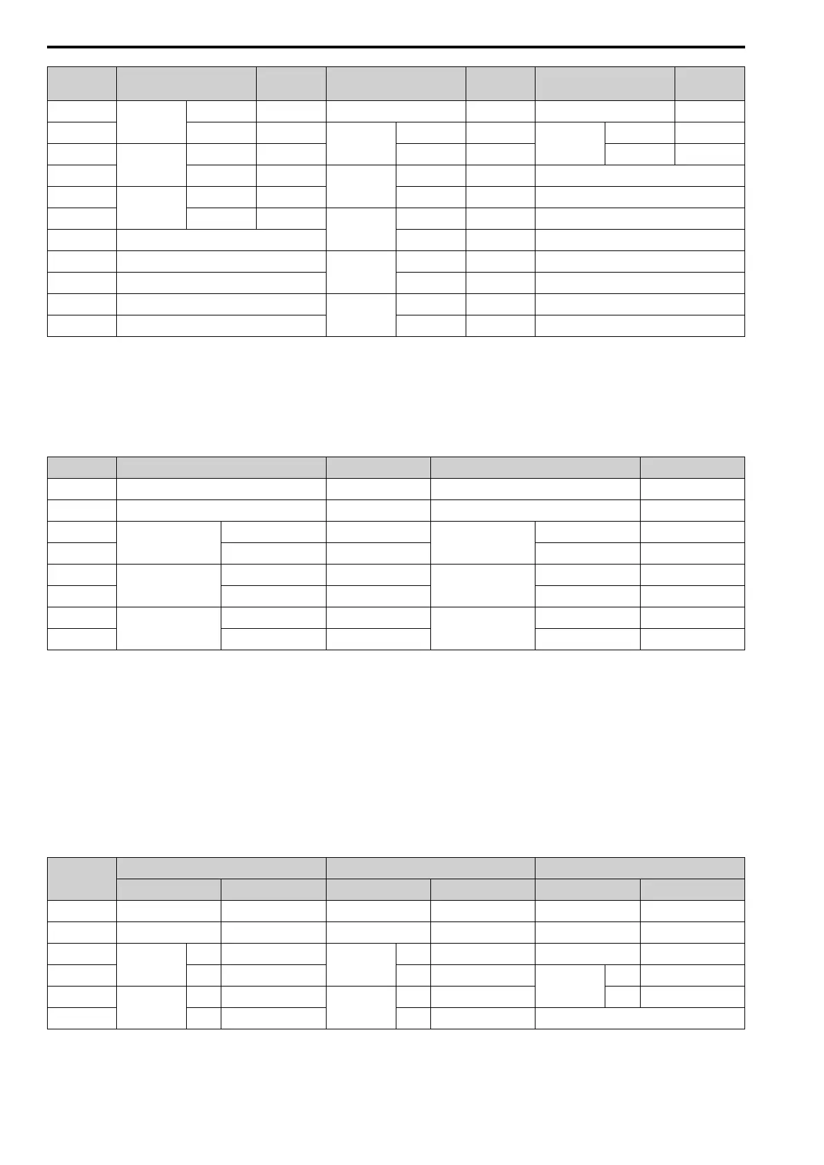
■ Loopback Test
The loopback test uses function code 08 (Hex.) and returns the command message as a response message. This
test checks communication between the master and slave. The test code and data can use desired values.
Table 6.8 shows examples of messages given out when the loopback test is done with the drive of slave 1.
Table 6.8 Message Examples from the Loopback Test
Byte Command Message
Setting Data (Hex.)
Response Message (Normal)
Setting Data (Hex.)
0 Slave address 01 Slave address 01
1 Function code 08 Function code 08
2
Test code
Upper 00
Test code
Upper 00
3 Lower 00 Lower 00
4
Data
Upper A5
Data
Upper A5
5 Lower 37 Lower 37
6
CRC-16
Upper DA
CRC-16
Upper DA
7 Lower 8D Lower 8D
■ Writing to Multiple Holding Registers
You can write the data that you set to the number of holding registers set in function code 10 (hex). You must
configure the number of the holding registers and each 8 higher bits and 8 lower bits in order in the command
message for the write data. You can write to a maximum of 16 holding registers.
Table 6.9 shows example messages when you use the PLC to set Forward run in the drive of slave 1 with a 60.00
Hz frequency reference.
When you rewrite the parameter value with the write command through the H5-11 [Comm ENTER Command
Mode] setting, you must use the Enter command to save and enable the contents of the changes. Refer to H5-11:
Comm ENTER Command Mode on page 682 and Enter Command on page 227 for more information.
Table 6.9 Message Example When Writing to Multiple Holding Registers
Byte
Command Message Response Message (When Normal) Response Message (When There is a Fault)
Setting Data (Hex.) Setting Data (Hex.) Setting Data (Hex.)
0 Slave address 01 Slave address 01 Slave address 01
1 Function code 10 Function code 10 Function code 90
2
Starting No.
Upper 00
Starting No.
Upper 00 Error code 02
3 Lower 01 Lower 01
CRC-16
Upper CD
4
Data Quantity
Upper 00
Data Quantity
Upper 00 Lower C1
5 Lower 02 Lower 02 -
 Loading...


