12.4 C: Tuning
564 YASKAWA SIEPC71061753C GA500 Technical Manual
Symptom Remedy
Wiring between the drive and motor is too long. Decrease the carrier frequency.
Note:
If the motor cable is too long, it can be necessary to decrease the carrier frequency. Refer to Table 12.41 for the
wiring distance and decrease the carrier frequency.
Audible motor noise is too loud.
Increase the carrier frequency. Use Swing PWM.
Note:
The default carrier frequency in ND is C6-02 = 7 [Swing PWM1 (Audible Sound 1)], with a 2 kHz base. You can
increase the carrier frequency in Normal Duty mode, but this will decrease the drive rated current.
Table 12.41 Wiring Distance
Wiring Distance 50 m (164 ft) Maximum 100 m (328 ft) Maximum More than 100 m (328 ft)
C6-02 [Carrier Frequency Selection] 1 to F (up to 15 kHz) 1 to 2 (up to 5 kHz), 7 1 (up to 2 kHz), 7
Note:
• If the length of the wire between the drive and an induction motor is longer than 100 m (328 ft), set A1-02 = 0 [V/f].
• The maximum wiring cable length between the drive and a PM motor is 100 m (328 ft).
• If the cable length between the drive and the motor is too long when A1-02 = 6, set A1-02 = 5.
■ C6-03: Carrier Frequency Upper Limit
No.
(Hex.)
Name Description
Default
(Range)
C6-03
(0225)
Carrier Frequency Upper
Limit
Sets the upper limit of the carrier frequency. Set C6-02 = F [Carrier Frequency Selection = User
Defined (C6-03 to C6-05)] to set this parameter.
Determined by C6-02
(1.0 - 15.0 kHz)
Setting a Fixed User-Defined Carrier Frequency
When you cannot use C6-02 to set a carrier frequency between set selectable values, you can set the value in C6-
03. The carrier frequency will be fixed to the value set to C6-03.
When A1-02 = 0 [Control Method Selection = V/f], set C6-03 = C6-04 [Carrier Frequency Lower Limit] to fix
the carrier frequency.
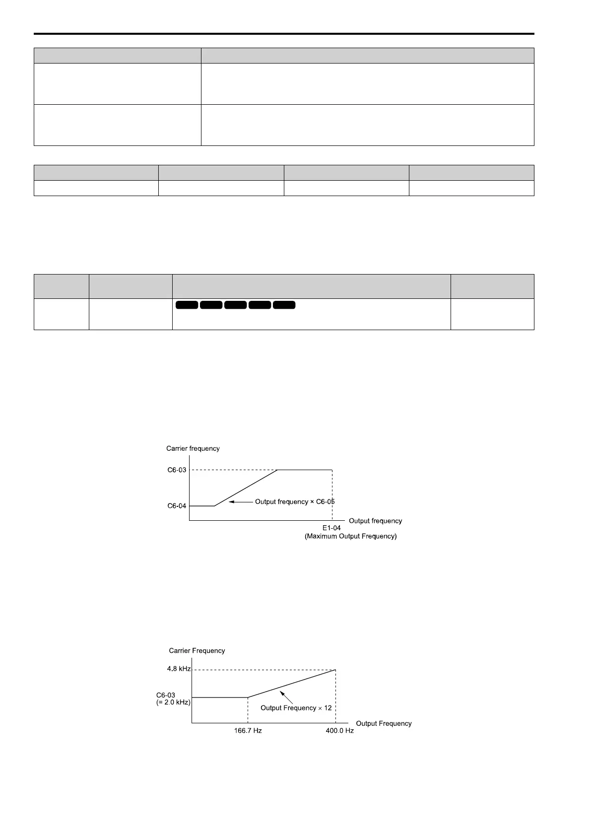
Setting a Variable Carrier Frequency to Agree with the Output Frequency
When A1-02 = 0, set C6-03, C6-04, and C6-05 [Carrier Freq Proportional Gain] as shown in Figure 12.47 to
make the carrier frequency change linearly with the output frequency.
Figure 12.47 Setting a Variable Carrier Frequency to Agree with the Output Frequency
Note:
• When C6-05 ≤ 7, the drive disables C6-04. The carrier frequency is fixed to the value set to C6-03.
• The drive detects oPE11 [Carrier Frequency Setting Error] when these conditions are correct at the same time:
–C6-05 ≥ 6
–C6-04 ≥ C6-03
• When A1-02 = 0, 2, 5, 8 [Control Method Selection = v/f, OLV, OLV/PM, EZOLV], in the area where the output frequency is more than
C6-03 and C6-12, the carrier frequency = output frequency × 12, and it will change with the output frequency.
Figure 12.48 Carrier Frequency when C6-03 = 2.0 kHz, E1-04 = 400.0 Hz
 Loading...


