16 Safe Disable Input
106 YASKAWA TOEPC71061737B GA800 Drive Installation & Primary Operation
The “Safe Torque Off” status is only possible with the Safe Disable function. Clear the Run command to stop the
drive. Turning off drive output (a baseblock condition) ≠ “Safe Torque Off”.
Note:
• When it is necessary to ramp to stop the motor, do not turn off terminals H1 and H2 until the motor fully stops. This will prevent the motor
from coasting to stop during usual operation.
• A maximum of 3 ms will elapse from when terminals H1 or H2 shut off until the drive switches to the “Safe Torque Off” status. Set the OFF
status for terminals H1 and H2 to hold for at least 2 ms. The drive may not be able to switch to the “Safe Torque Off” status if terminals H1
and H2 are only open for less than 2 ms.
Going from “Safe Torque Off” to Usual Operation
The safety input will only release when there is no Run command.
• During Stop
When the Safe Disable function is triggered during stop, close the circuit between terminals H1-HC and H2-HC to
disable “Safe Torque Off”. Enter the Run command after the drive stops correctly.
• During Run
When the Safe Disable function is triggered during run, close the circuit between terminals H1-HC and H2-HC to
disable “Safe Torque Off” after clearing the Run command. Enter the Stop command, then enter the Run command
when terminals H1 and H2 are ON or OFF.
■ Safe Disable Monitor Output Function and Keypad Display
Refer to Table 16.3 for information about the relation between the input channel status, Safety monitor output status,
and drive output status.
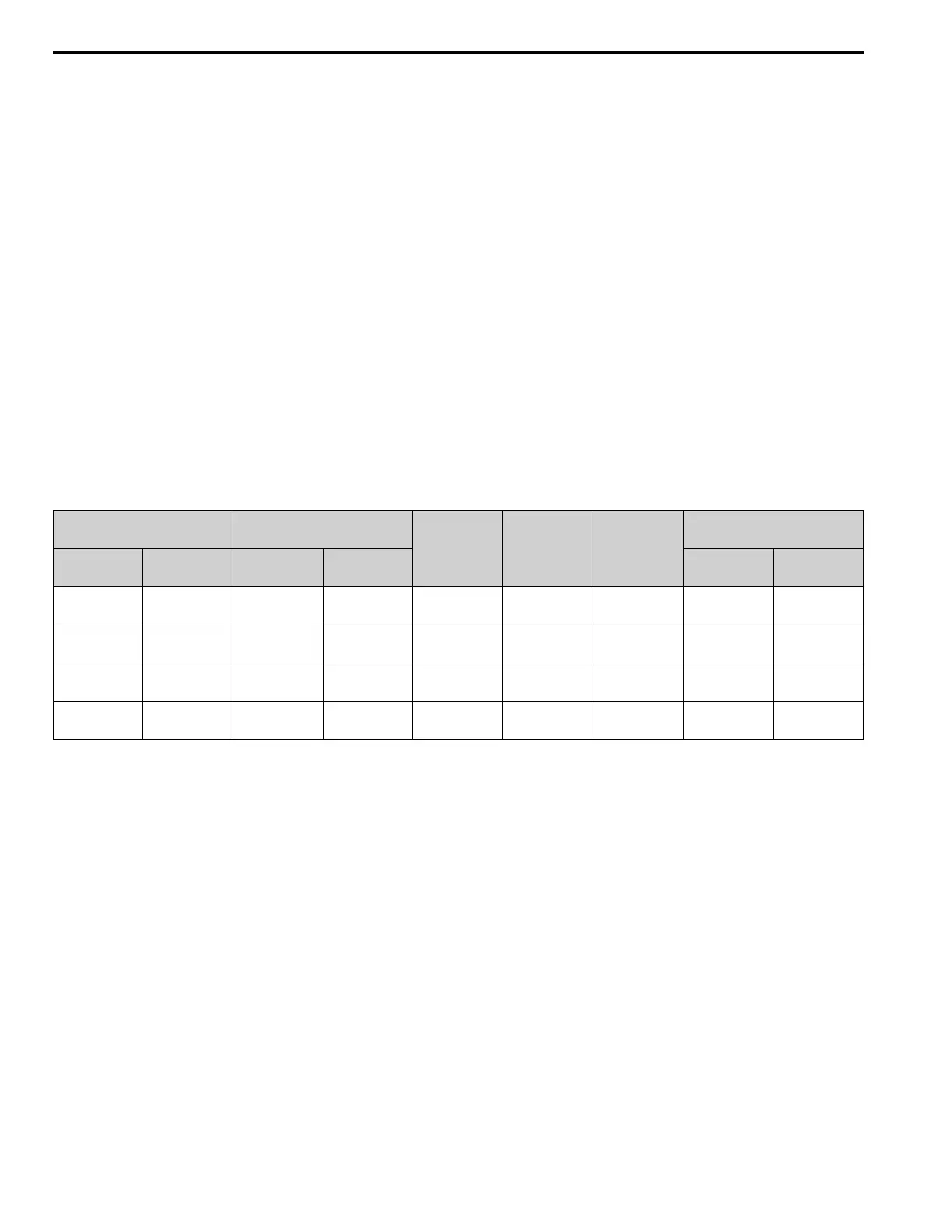
Table 16.3 Safe Disable Input and External Device Monitor (EDM) Terminal Status
Input Channel Status Safety Monitor Output Status
Drive Output
Status
Keypad Display
LED Status
Ring
MEMOBUS Register
0020H
Input 1
(H1-HC)
Input 2
(H2-HC)
MFDO Terminal
(H2-xx = 21)
MFDO Terminal
(H2-xx = 121)
bit C bit D
ON
(Close the circuit)
ON
(Close the circuit)
OFF ON
Baseblock
(Drive ready)
Normally
displayed
Ready:
Illuminated
0 0
OFF
(Open)
ON
(Close the circuit)
OFF ON
Safety status
(STo)
SToF
(Flashing)
ALM/ERR:
Flashing
1 0
ON
(Close the circuit)
OFF
(Open)
OFF ON
Safety status
(STo)
SToF
(Flashing)
ALM/ERR:
Flashing
1 0
OFF
(Open)
OFF
(Open)
ON OFF
Safety status
(STo)
STo
(Flashing)
Ready: Flashing 0 1
Safety Function Status Monitor
The drive Safety monitor output sends a feedback signal about the status of the Safety function. The Safety monitor
output is one of the possible settings available for the MFDO terminals. If there is damage to the Safe Disable circuit,
a controller (PLC or safety relay) must read this signal as an input signal to hold the “Safe Torque Off” status. This
will help verify the condition of the safety circuit. Refer to the manual for the safety device for more information
about the Safety function.
It is possible to switch polarity of the Safety monitor output signal with the MFDO function settings. Refer to Table
16.3 for setting instructions.
Keypad Display
If the two input channels are OFF (Open), the keypad will flash STo [Safe Torque OFF].
If there is damage to the Safe disable circuit or the drive, the keypad will flash SToF [Safe Torque OFF Hardware]
when one input channel is OFF (Open), and the other is ON (Short circuit). When you use the Safe disable circuit
correctly, the keypad will not show SToF.
If there is damage to the drive, the keypad will show SCF [Safety Circuit Fault] when the drive detects a fault in the
Safe disable circuit. Refer to the chapter on Troubleshooting for more information.
■ Validating the Safe Disable Function
After you replace parts or do maintenance on the drive, first complete all necessary wiring to start the drive, then test
the Safe Disable input with these steps. Keep a record of the test results.

 Loading...


