6 Mechanical Installation
18 YASKAWA TOEPC71061737B GA800 Drive Installation & Primary Operation
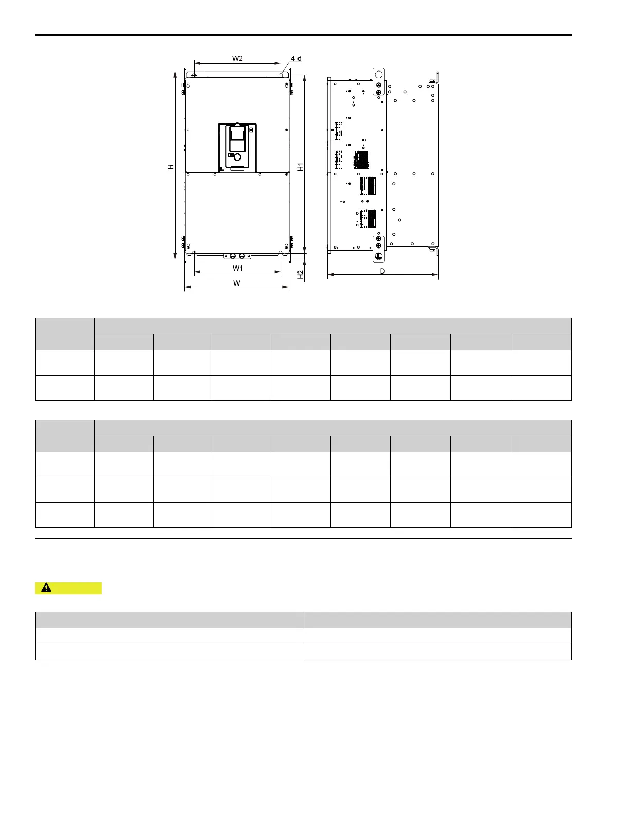
Table 6.5 IP20 Exterior and Mounting Dimensions for Models 2257 to 2415
Model
Dimensions mm (in)
W H D W1 W2 H1 H2 d
2257 - 2313
312
(12.28)
700
(27.56)
420
(16.54)
218
(8.58)
218
(8.58)
659
(25.94)
28
(1.10)
M10
2360 - 2415
440
(17.32)
800
(31.50)
472
(18.58)
370
(14.57)
370
(14.57)
757
(29.80)
28
(1.10)
M12
Table 6.6 IP20 Exterior and Mounting Dimensions for Models 4208 to 4720
Model
Dimensions mm (in)
W H D W1 W2 H1 H2 d
4208 - 4302
312
(12.28)
700
(27.56)
420
(16.54)
218
(8.58)
218
(8.58)
659
(25.94)
28
(1.10)
M10
4371 - 4414
440
(17.32)
800
(31.50)
472
(18.58)
370
(14.57)
370
(14.57)
757
(29.80)
28
(1.10)
M12
4477 - 4720
510
(20.08)
1136
(44.72)
480
(18.90)
450
(17.72)
450
(17.72)
1093
(43.03)
25.5
(1.00)
M12
◆ Moving the Drive
Obey local laws and regulations when moving and installing this product.
CAUTION
Crush Hazard. Tighten terminal cover screws and hold the case safely when you move the drive. If the drive or
covers fall, it can cause moderate injury.
Drive Weight Persons Necessary to Move the Drive
< 15 kg (33 lb) 1
≥ 15 kg (33 lb) 2 + using appropriate lifting equipment
Refer to the Technical Reference for information about how to use suspension systems, wires, or hanging metal
brackets to move the drive.

 Loading...


