13 European Standards
YASKAWA TOEPC71061737B GA800 Drive Installation & Primary Operation 89
*4 Reinforced insulation separates the output terminals from other circuits. Users can also connect circuits that are not Safety Extra-Low
Voltage circuits if the drive output is 250 Vac 1 A maximum or 30 Vdc 1 A maximum.
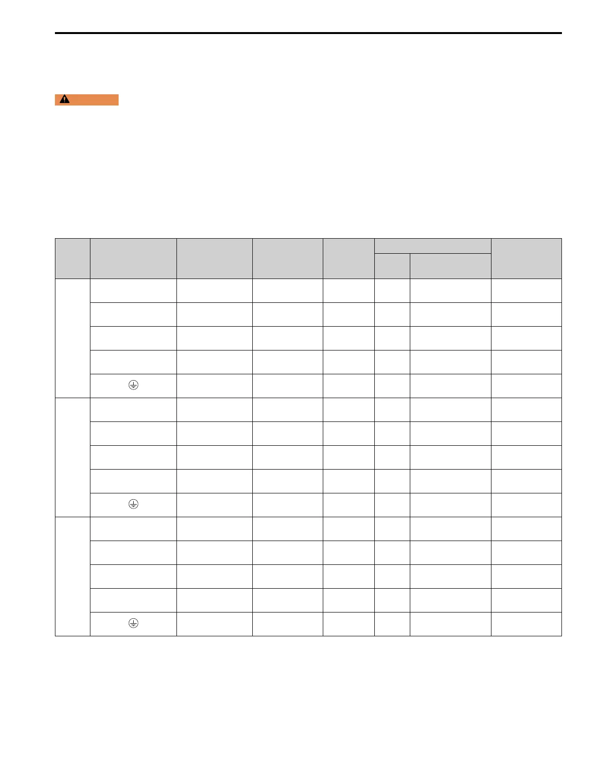
■ Main Circuit Wire Gauges and Tightening Torques
WARNING
Electrical Shock Hazard. Only connect peripheral options, for example a DC link choke or braking resistor, to
terminals +1, +2, +3, -, B1, and B2. Incorrect wiring can cause serious injury or death.
Note:
• The recommended wire gauges are based on drive continuous current ratings with 75 °C (167 °F) 600 V class 2 heat-resistant indoor PVC
wire. Assume these conditions:
–Ambient temperature: 40 °C (104 °F) maximum
–Wiring distance: 100 m (328 ft) maximum
–Normal Duty rated current value
• Refer to the instruction manual for each device for recommended wire gauges to connect peripheral devices or options to terminals +1, +2,
+3, -, B1, and B2. Contact Yaskawa or your nearest sales representative if the recommended wire gauges for the peripheral devices or
options are out of the range of the applicable gauges for the drive.
Three-Phase 200 V Class
Model Terminals
Recommended
Gauge
mm
2
Applicable Gauge
(IP20 Applicable
Gauge
*1
)
mm
2
Wire Stripping
Length
*2
mm
Terminal Screw
Tightening Torque
N∙m (in∙lb)
Size Shape
2004
R/L1, S/L2, T/L3 2.5
2.5 - 10
(2.5 - 10)
10 M4 Slotted (-)
1.5 - 1.7
(13.5 - 15)
U/T1, V/T2, W/T3 2.5
2.5 - 10
(2.5 - 10)
10 M4 Slotted (-)
1.5 - 1.7
(13.5 - 15)
-, +1, +2 2.5
2.5 - 16
(2.5 - 16)
18 M5 Slotted (-)
2.3 - 2.5
(19.8 - 22)
*3
B1, B2 2.5
2.5 - 4
(2.5 - 4)
10 M4 Slotted (-)
1.5 - 1.7
(13.5 - 15)
2.5
*4
2.5 - 10
(-)
- M4 Phillips/slotted combo
1.2 - 1.5
(10.6 - 13.3)
2006
R/L1, S/L2, T/L3 2.5
2.5 - 10
(2.5 - 10)
10 M4 Slotted (-)
1.5 - 1.7
(13.5 - 15)
U/T1, V/T2, W/T3 2.5
2.5 - 10
(2.5 - 10)
10 M4 Slotted (-)
1.5 - 1.7
(13.5 - 15)
-, +1, +2 2.5
2.5 - 16
(2.5 - 16)
18 M5 Slotted (-)
2.3 - 2.5
(19.8 - 22)
*3
B1, B2 2.5
2.5 - 4
(2.5 - 4)
10 M4 Slotted (-)
1.5 - 1.7
(13.5 - 15)
2.5
*4
2.5 - 10
(-)
- M4 Phillips/slotted combo
1.2 - 1.5
(10.6 - 13.3)
2008
R/L1, S/L2, T/L3 2.5
2.5 - 10
(2.5 - 10)
10 M4 Slotted (-)
1.5 - 1.7
(13.5 - 15)
U/T1, V/T2, W/T3 2.5
2.5 - 10
(2.5 - 10)
10 M4 Slotted (-)
1.5 - 1.7
(13.5 - 15)
-, +1, +2 2.5
2.5 - 16
(2.5 - 16)
18 M5 Slotted (-)
2.3 - 2.5
(19.8 - 22)
*3
B1, B2 2.5
2.5 - 4
(2.5 - 4)
10 M4 Slotted (-)
1.5 - 1.7
(13.5 - 15)
2.5
*4
2.5 - 10
(-)
- M4 Phillips/slotted combo
1.2 - 1.5
(10.6 - 13.3)

 Loading...


