6 Mechanical Installation
YASKAWA TOEPC71061737B GA800 Drive Installation & Primary Operation 21
Different drive models have different procedures to remove and reattach the covers. Refer to Table 6.7 for more
information.
Table 6.7 Procedures to Remove Covers by Drive Model
Model Procedure Reference
2004 - 2211
4002 - 4168
Procedure A 21
2257 - 2415
4208 - 4720
Procedure B 22
■ Removing/Reattaching the Cover Using Procedure A
DANGER
Electrical Shock Hazard. Do not examine, connect, or disconnect wiring on an energized drive. Before servicing,
disconnect all power to the equipment and wait for the time specified on the warning label at a minimum. The internal capacitor
stays charged after the drive is de-energized. The charge indicator LED extinguishes when the DC bus voltage decreases below 50
Vdc. When all indicators are OFF, remove the covers before measuring for dangerous voltages to make sure that the drive is safe. If
you do work on the drive when it is energized, it will cause serious injury or death from electrical shock. The drive has internal
capacitors that stay charged after you de-energize the drive.
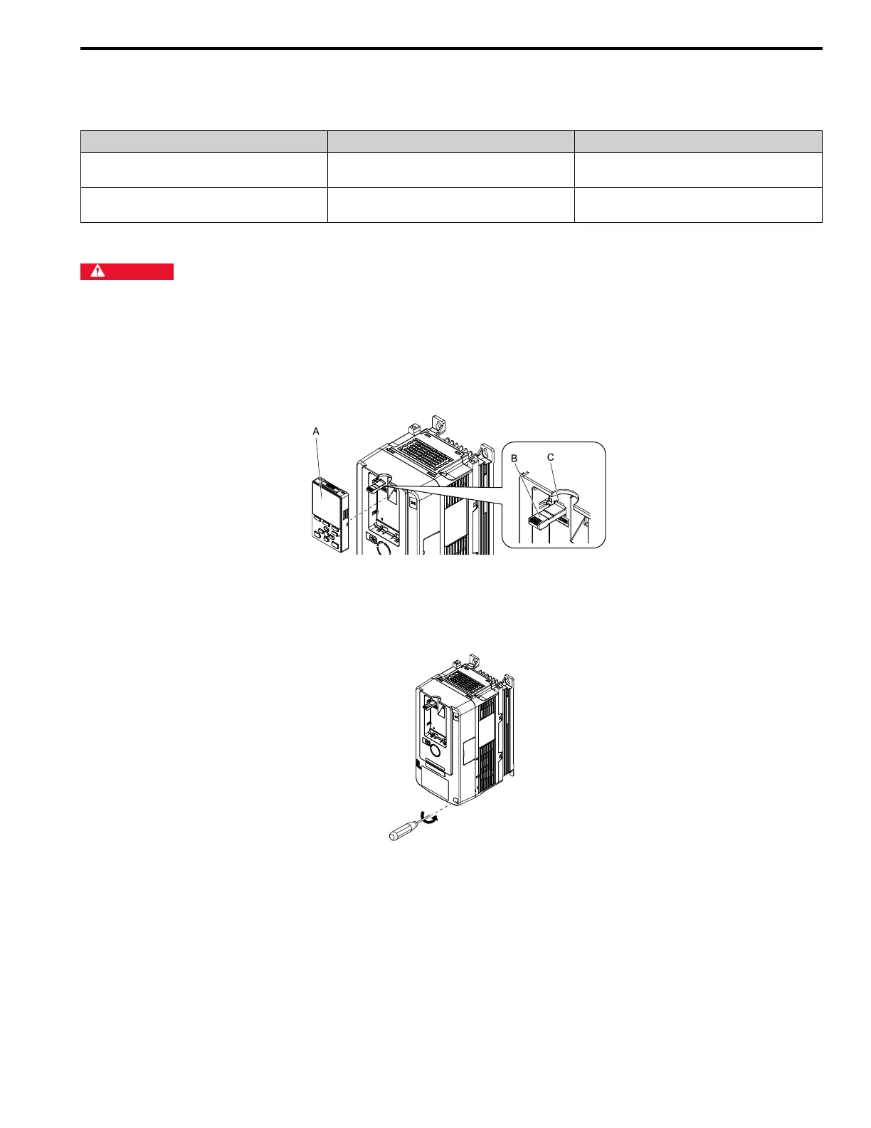
Remove the Front Cover
1. Remove the keypad and the keypad connector, then insert the end of the keypad connector that has the tab
into the keypad connector holder on the front cover.
A - Keypad
B - Keypad connector
C - Holder
Figure 6.5 Remove the Keypad and Keypad Connector
2. Loosen the front cover screws.
Figure 6.6 Loosen the Front Cover Screws

 Loading...


