19 Troubleshooting
YASKAWA TOEPC71061737B GA800 Drive Installation & Primary Operation 119
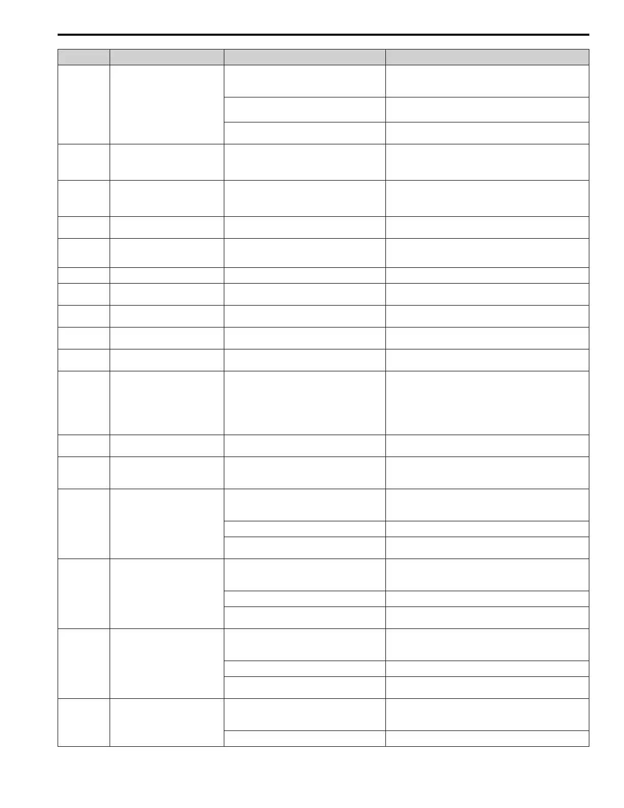
Code Name Causes Possible Solutions
The communication protocol is not compatible. • Examine the values set in H5-xx.
• Examine the settings on the controller side and correct the
difference in communication conditions.
The value set in H5-09 [CE Detection Time] is too
small for the communications cycle.
• Change the controller software settings.
• Increase the value set in H5-09.
The controller software or hardware is causing a
communication problem.
Examine the controller and remove the cause of the problem.
CP1 Comparator 1 Limit Error
The monitor value set in H2-20 [Comparator 1
Monitor Selection] was in the range of H2-21
[Comparator 1 Lower Limit] and H2-22
[Comparator 1 Upper Limit].
Examine the monitor value and remove the cause of the error.
CP2 Comparator 2 Limit Error
The monitor value set in H2-26 [Comparator 2
Monitor Selection] was outside the range of H2-27
[Comparator 2 Lower Limit] and H2-28
[Comparator 2 Upper Limit].
Examine the monitor value and remove the cause of the error.
CrST Cannot Reset
The drive received a fault reset command when a Run
command was active.
Turn off the Run command then de-energize and re-energize the
drive.
CyC
MECHATROLINK
CommCycleSettingErr
The communications cycle setting of the controller is
not in the permitted range of the MECHATROLINK
interface option.
Set the communications cycle of the controller in the permitted
range of the MECHATROLINK interface option.
dEv Speed Deviation
The load is too heavy Decrease the load.
dnE Drive Disabled
A terminal set for H1-xx = 6A [Drive Enable] turned
OFF.
Examine the operation sequence.
dWAL DriveWorksEZ Alarm
There was an error in the DriveWorksEZ program. Examine the DriveWorksEZ program and remove the cause of the
error. This is not a drive fault.
dWA2 DriveWorksEZ Alarm 2
The DriveWorksEZ program output a minor fault. Examine the DriveWorksEZ program and remove the cause of the
fault. This is not a drive fault.
dWA3 DriveWorksEZ Alarm 3
The DriveWorksEZ program output a minor fault. Examine the DriveWorksEZ program and remove the cause of the
fault. This is not a drive fault.
E5
MECHATROLINK Watchdog Timer
Err
The drive detected a watchdog circuit exception while
it received data from the controller.
Examine the MECHATROLINK cable connection. If this error
occurs frequently, examine the wiring and decrease the effects of
electrical interference as specified by these manuals:
• MECHATROLINK-II Installation Guide (MECHATROLINK
Members Association, manual number MMATDEP011)
• MECHATROLINK-III Installation Manual (MECHATROLINK
Members Association, publication number MMATDEP018)
EF
FWD/REV Run Command Input
Error
A forward command and a reverse command were
input at the same time for longer than 0.5 s.
Examine the forward and reverse command sequence and correct
the problem.
EF0 Option Card External Fault
The communication option card received an external
fault from the controller.
1. Find the device that caused the external fault and remove the
cause.
2. Clear the external fault input from the controller.
EF1 External Fault (Terminal S1)
MFDI terminal S1 caused an external fault through an
external device.
1. Find the device that caused the external fault and remove the
cause.
2. Clear the external fault input in the MFDI.
The wiring is incorrect. Correctly connect the signal line to MFDI terminal S1.
External Fault [H1-01 = 2C to 2F] is set to MFDI
terminal S1, but the terminal is not in use.
Correctly set the MFDI.
EF2 External Fault (Terminal S2)
MFDI terminal S2 caused an external fault through an
external device.
1. Find the device that caused the external fault and remove the
cause.
2. Clear the external fault input in the MFDI.
The wiring is incorrect. Correctly connect the signal line to MFDI terminal S2.
External Fault [H1-02 = 2C to 2F] is set to MFDI
terminal S2, but the terminal is not in use.
Correctly set the MFDI.
EF3 External Fault (Terminal S3)
MFDI terminal S3 caused an external fault through an
external device.
1. Find the device that caused the external fault and remove the
cause.
2. Clear the external fault input in the MFDI.
The wiring is incorrect. Correctly connect the signal line to MFDI terminal S3.
External Fault [H1-03 = 2C to 2F] is set to MFDI
terminal S3, but the terminal is not in use.
Correctly set the MFDI.
EF4 External Fault (Terminal S4)
MFDI terminal S4 caused an external fault through an
external device.
1. Find the device that caused the external fault and remove the
cause.
2. Clear the external fault input in the MFDI.
The wiring is incorrect. Correctly connect the signal line to MFDI terminal S4.

 Loading...


