8-3
170625-1CD
HW1482737
ES200RD II
8 Electrical Equipment Specification
8.2 Internal Connections
8.2 Internal Connections
Highly reliable connectors are equipped on each connection part of the
manipulator to enable easy removal and installation for maintenance and
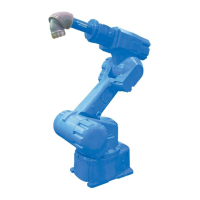
inspection. For the number and location of connectors, see Fig. 8-4
“Locations and Numbers of Connectors”.
Diagrams for internal connections of the manipulator are shown in Fig.
8-5(a) "Internal Connection Diagram" on page 8-4 and Fig. 8-5(b) "Internal
Connection Diagram" on page 8-5.
Fig. 8-4: Locations and Numbers of Connectors
Connector for internal user
I/O wiring harness (Base)
Connector for external axis
(Power cable)
Connector for external axis
(Encoder cable)
Connector for internal user
I/O wiring harness (Casing)
S1
AIR
2BC
1BC
S1
AIR
2BC
1BC
1BC
2BC
Table 8-1: List of Connector Types
Name Type of Connector
Connector Base Connector for internal
user I/O wiring harness
JL05-2A28-21PC
(JL05-6A28-21S: Optional)
U-arm Connector for internal
user I/O wiring harness
JL05-2A22-14SC
(JL05-6A22-14P: Optional)
Connector for external axis
(Encoder cable)
JL05-2A20-29SC
(JL05-6A20-29P: Optional)
Connector for external axis
(Power cable)
JL05-2A18-1SC
(JL05-6A18-1P: Optional)

 Loading...
