6-32
Setting Example
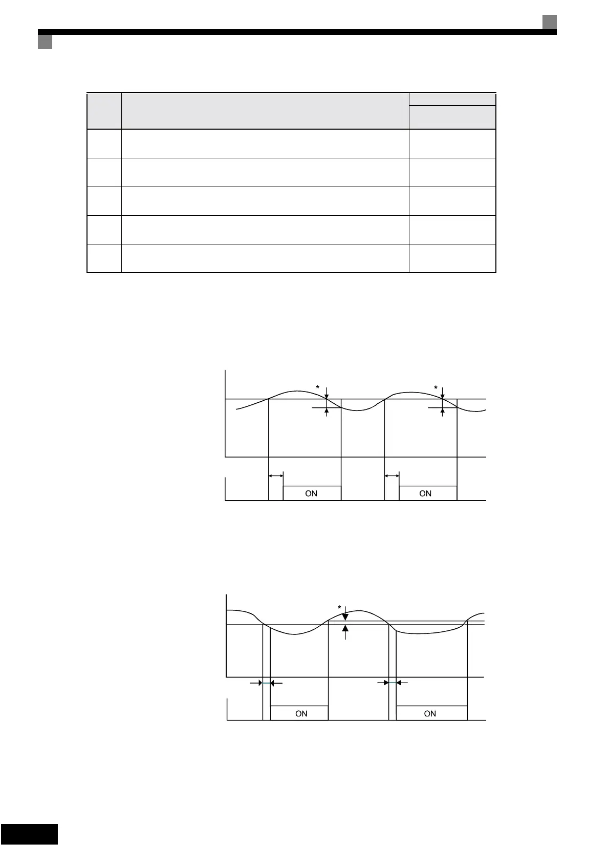
The following diagram shows the time chart for overtorque and undertorque detection.
• Overtorque Detection
• Undertorque Detection
4
Overtorque detected continuously during operation; output is stopped upon
detection.
OL3 lights up
5
Undertorque detection only with speed agree; operation continues (warning
is output).
UL3 flashes
6
Undertorque detected continuously during operation; operation continues
(warning is output).
UL3 flashes
7
Undertorque detection only with speed matching; output is stopped upon
detection.
UL3 lights up
8
Undertorque detected continuously during operation; output is stopped upon
detection.
UL3 lights up
Set
Value
Function
Operator
Overtorque/ Under-
torque Detection 1
Motor current (output torque)
L6-02
L6-03
L6-03
Overtorque detection 1 NO
*Overtorque detection switch off bandwidth is approximately 10% of the Inverter rated
output current (or motor rated torque).
Motor current (output torque)
L6-02
L6-03
L6-03
Undertorque detection 1 NO
*Undertorque detection switch off bandwidth is approximately 10% of the Inverter rated
output current (or motor rated torque).
Artisan Technology Group - Quality Instrumentation ... Guaranteed | (888) 88-SOURCE | www.artisantg.com