Individual Functions
6-81
Self-Diagnosis
The Inverter has a built-in function for self-diagnosing the functioning of the serial communication interface
circuits. This function is called the self-diagnosis function. It uses the connected communications parts of the
send and receive terminals to receive data sent by the Inverter and thereby to check if communication is per-
formed normally.
To perform the self-diagnosis function use the following procedure.
1. Turn ON the inverter power supply, and set 67 (communications test mode) in constant H1-05 (Terminal
S7 Function Selection).
2. Turn OFF the inverter power supply.
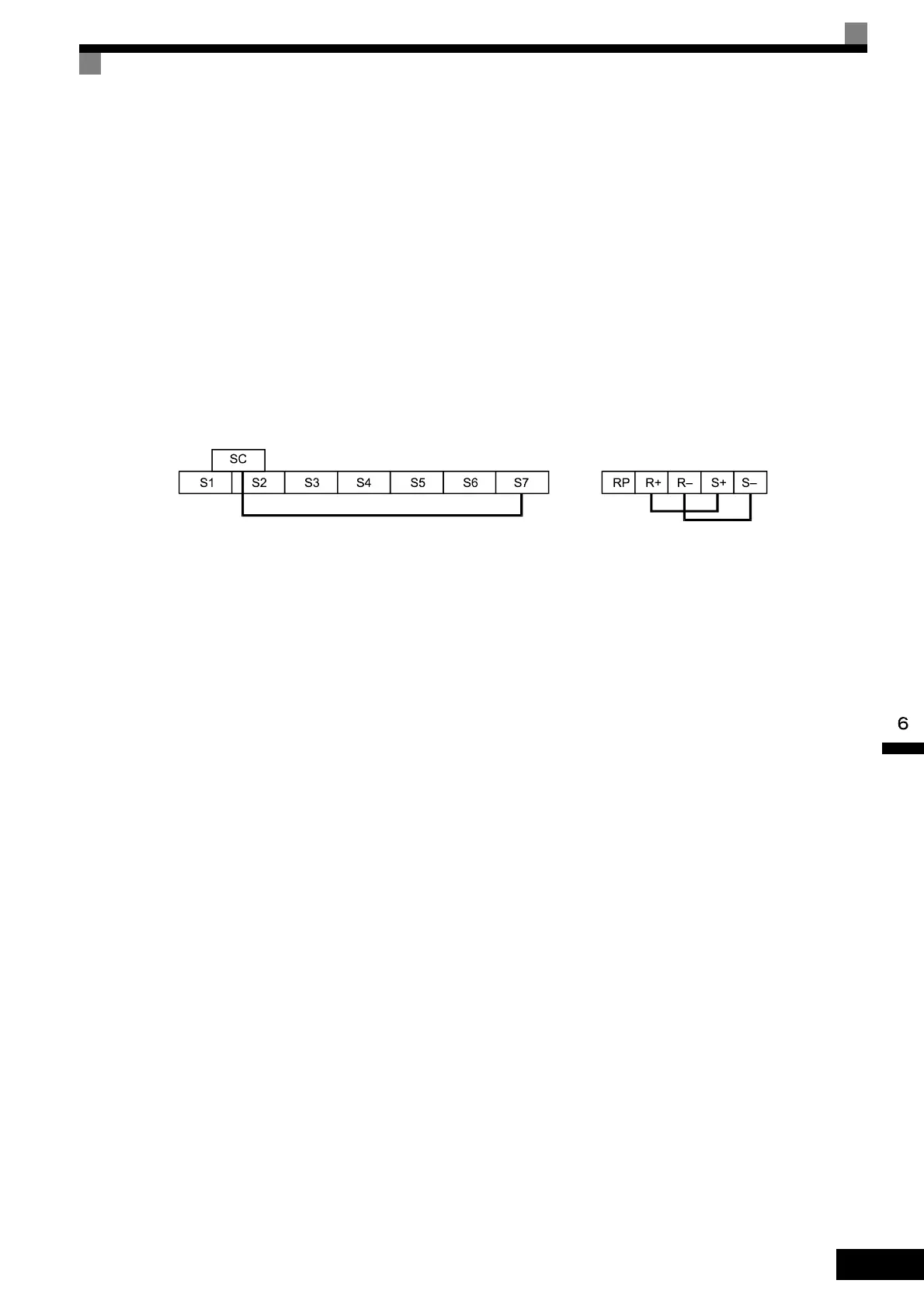
3. Perform the wiring according to Fig 6.46.
4. Turn ON the terminating resistance. (Turn ON pin 1 on DIP switch 1.)
5. Turn ON the inverter power supply.
Fig 6.46 Communication Terminals Wiring for Self-Diagnosis
During normal operation, the Digital Operator displays “PASS” on the display.
If an error occurs, a “CE” (MEMOBUS communications error) alarm will be displayed on the Digital Opera-
tor, the error contact output will be turned ON, and the Inverter operation ready signal will be turned OFF.
Artisan Technology Group - Quality Instrumentation ... Guaranteed | (888) 88-SOURCE | www.artisantg.com