2-22
* 1. The default settings are given for terminals S3 to S7. For a 3-wire sequence, the default settings are a 3-wire sequence for S5, multi-step speed setting 1
for S6 and multi-step speed setting 2 for S7.
* 2. Do not use this power supply for supplying any external equipment.
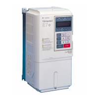
* 3. When driving a reactive load, such as a relay coil with DC power supply, always insert a flywheel diode as shown in Fig 2.12.
Fig 2.12 Flywheel Diode Connection
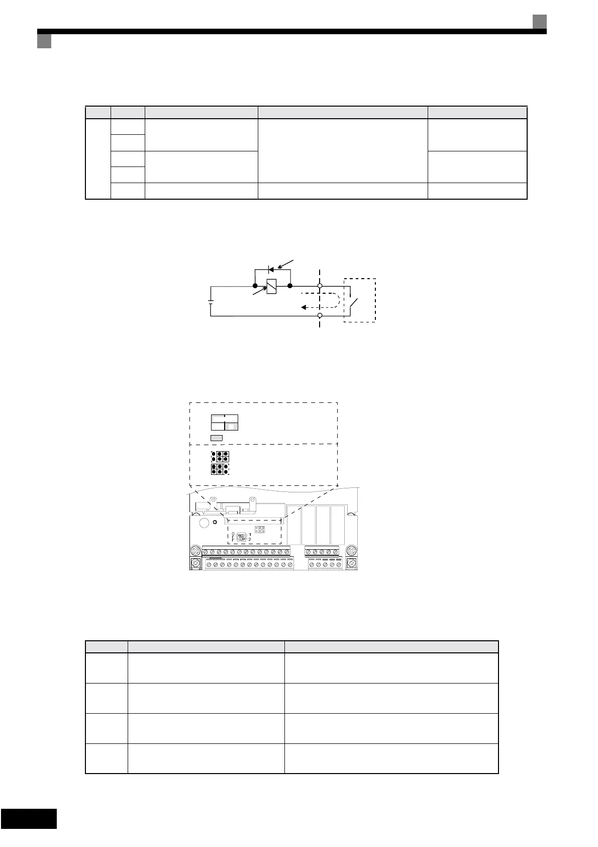
Jumper CN15 and DIP Switch S1
The jumper CN 15 and DIP switch S1 are described in this section.
Fig 2.13 Jumper CN15 and DIP Switch S1
The functions of DIP switch S1 and jumper CN15 are shown in the following table.
*CN15 is not available on the standard terminal board. An optional terminal board which has this jumper is available.
RS-
485/
422
R+
MEMOBUS communica-
tions input
For 2-wire RS-485, short R+ and S+ as well
as R- and S-.
Differential input, PHC
isolation
R-
S+
MEMOBUS communica-
tions output
Differential input, PHC
isolation
S-
IG Signal common – –
Table 2.12 DIP Switch S1 and jumper CN15
Name Function Setting
S1-1
RS-485 and RS-422 terminating resis-
tance
OFF: No terminating resistance
ON: Terminating resistance of 110 Ω
S1-2 Input method for analog input A2
V: 0 to 10 V (internal resistance: 20 kΩ)
I: 0/4 to 20 mA (internal resistance: 250 Ω)
CN15-
CH1*
Multifunction analog output FM voltage/
current switch
I: Current output
V: Voltage output
CN15-
CH2*
Multifunction analog output AM voltage/
current switch
I: Current output
V: Voltage output
Table 2.11 Control Circuit Terminals with default settings (Continued)
Type
No. Signal Name Function Signal Level
External power:
30 VDC max.
Coil
Flywheel diode
1 A max.
The rating of the flywheel diode
must be at least as high as the
circuit voltage.
Note: Refer to Table 2.12 for S1
functions.
: Factory settings
Terminating resistance
Analog input A2 switch
S1
CN15
ON
V
OFF
I
CN15
S1
Voltage output
Current output
Analog output switch*
CH1
CH2
CH1
CH2
}
}
IV
Artisan Technology Group - Quality Instrumentation ... Guaranteed | (888) 88-SOURCE | www.artisantg.com