5
-42
* When the control method is changed, the factory setting will change. The flux vector factory setting is given.
Analog Reference Board: F2
User constants for the Analog Reference Board are shown in the following table.
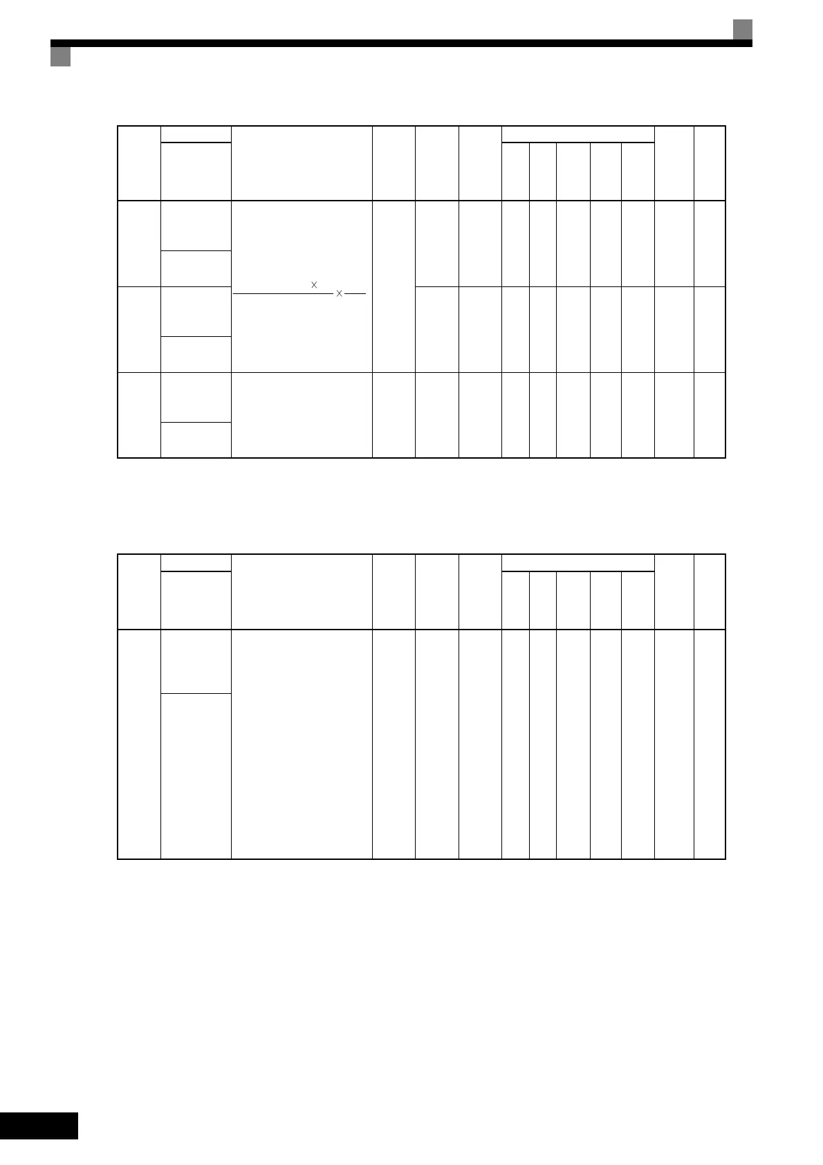
F1-12
Number of
PG gear teeth
1
Sets the number of teeth on
the gears if there are gears
between the PG and the
motor.
A gear ratio of 1 will be used
if either of F1-12 or F1-13
constant is set to 0.
0 to
1000
0 No No A No No No 38BH
6-161
PG # Gear
Teeth1
F1-13
Number of
PG gear teeth
2
0 No No A No No No 38CH
6-161
PG # Gear
Teeth2
F1-14
PG open-cir-
cuit detection
time
Used to set the PG disconnec-
tion detection time. PGO will
be detected if the detection
time continues beyond the set
time.
0.0 to
10.0
2.0 s No No A No A No 38DH
6-161
PGO Detect
Time
Con-
stant
Number
Name
Description
Setting
Range
Factory
Setting
Change
during
Opera-
tion
Control Methods
MEMO-
BUS
Regis-
ter
Page
Display
V/f
V/f
with
PG
Open
Loop
Vec-
tor
1
Flux
Vec-
tor
Open
Loop
Vec-
tor
2
F2-01
Bi-polar or
uni-polar
input selec-
tion
Sets the functions for channel
1 to 3 which are effective
when the AI-14B Analog
Reference Board is used.
0: 3-channel individual
(Channel 1: terminal A1,
Channel 2: terminal A2,
Channel 3: terminal A3)
1: 3-channel addition (Addi-
tion values are the fre-
quency reference)
When set to 0, select 1 for b1-
01. In this case the multi-
function input “Option/
Inverter selection” cannot be
used.
0 or 1 0 No A A A A A 38FH
6-167
AI-14 Input
Sel
Con-
stant
Number
Name
Description
Setting
Range
Factory
Setting
Change
during
Opera-
tion
Control Methods
MEMO-
BUS
Regis-
ter
Page
Display
V/f
V/f
with
PG
Open
Loop
Vec-
tor
1
Flux
Vec-
tor
Open
Loop
Vec-
tor
2
Input pulses from PG 60 F1-13
F1-01 F1-12
TOE-S616-60.1.book 42 ページ 2017年8月4日 金曜日 午後3時41分

 Loading...


