5
-52
* 1. Applicable for G7-Series Inverters with software versions PRG 1039 and later.
* 2. Applicable for G7-Series Inverters with software versions PRG 1038 and later.
Analog Inputs: H3
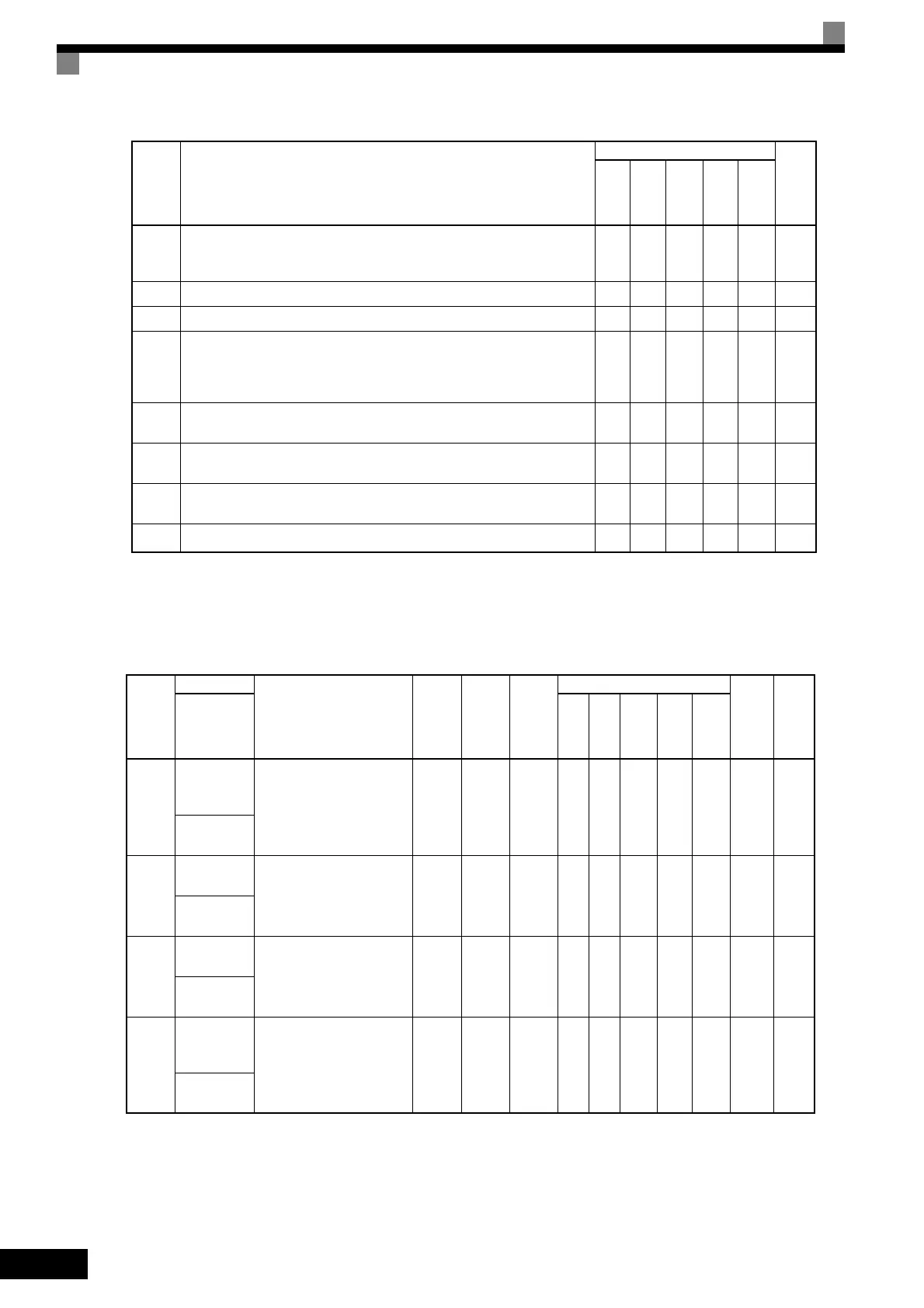
User constants for analog inputs are shown in the following table.
2F
*1
Maintenance Time
ON: The operation time of either the electrolytic capacitors or the cooling fan has
reached the specified maintenance time.
Yes Ye s Yes Ye s Yes –
30 During torque limit (current limit) (ON: During torque limit) No No Yes Yes Yes –
31 During speed limit (ON: During speed limit) No No No Yes No 6-88
32
Speed control circuit operating for torque control (except when stopped).
The external torque reference will be limited if torque control is selected (internal
torque reference < external torque reference).
Output when the motor is rotating at the speed limit.
No No No Yes Yes
6-131
33 Zero-servo end (ON: Zero-servo function completed) No No No Yes No
6-88
6-148
36
*2
Frequency (FOUT) detection 5 (ON: Output frequency ≥ + L4-01 or output
frequency ≤ L4-01, L4-02 used, OFF: during baseblock
Yes Ye s Yes Ye s Yes 6-5 1
37
During run 2 (ON: Frequency output, OFF: Base block, DC injection braking, ini-
tial excitation, operation stop)
Yes Ye s Yes Ye s Yes 6-8 7
3D
*2
Inverter's Cooling Fan Fault detected Yes Yes Yes Yes Yes 6-74
Con-
stant
Number
Name
Description
Setting
Range
Factory
Setting
Change
during
Opera-
tion
Control Methods
MEMO-
BUS
Regis-
ter
Page
Display
V/f
V/f
with
PG
Open
Loop
Vec-
tor
1
Flux
Vec-
tor
Open
Loop
Vec-
tor
2
H3-01
Signal level
selection (ter-
minal A1)
0: 0 to 10 V
1: -10V to 10 V
[11-bit + polarity (posi-
tive/negative) input]
0 or 1 0 No A A A A A 410H 6-28
Term A1
Signal
H3-02
Gain (termi-
nal A1)
Sets the frequency when 10 V
is input, as a percentage of the
maximum output frequency.
0.0 to
1000.0
100.0% Yes A A A A A 411H 6-28
Terminal A1
Gain
H3-03
Bias (termi-
nal A1)
Sets the frequency when 0 V
is input, as a percentage of the
maximum frequency.
-100.0
to
+100.0
0.0% Yes A A A A A 412H 6-28
Terminal A1
Bias
H3-04
Signal level
selection (ter-
minal A3)
0: 0 to 10 V
1: -10 V to 10 V
[11-bit + polarity (posi-
tive/negative) input]
0 or 1 0 No A A A A A 413H
6-28
6-130
Term A3
Signal
Set-
ting
Value
Function
Control Methods
Page
V/f
V/f
with
PG
Open
Loop
Vec-
tor
1
Flux
Vec-
tor
Open
Loop
Vec-
tor
2
TOE-S616-60.1.book 52 ページ 2017年8月4日 金曜日 午後3時41分

 Loading...


