5
-60
Power Loss Ridethrough: L2
User constants for power loss ridethroughs are shown in the following table.
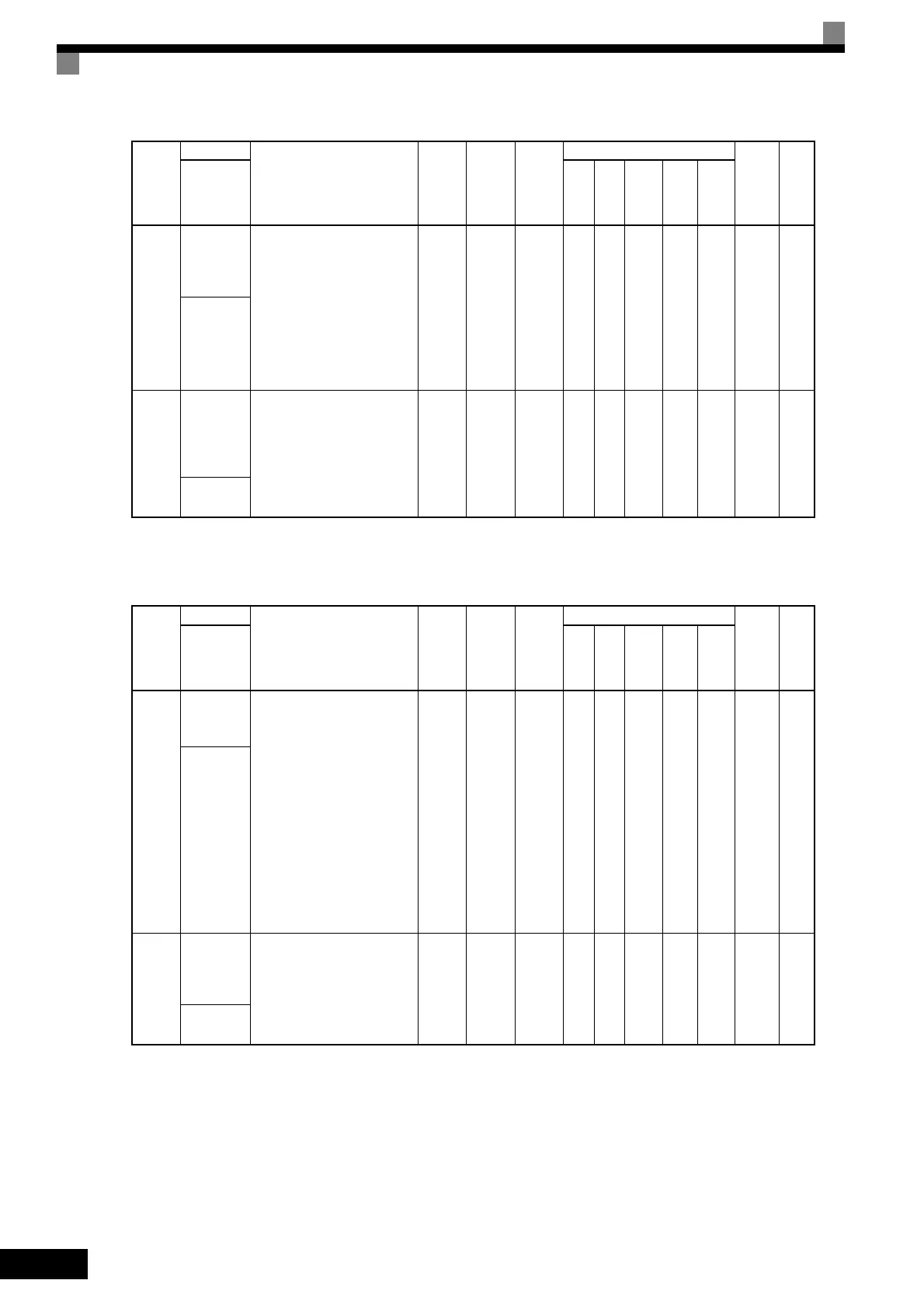
L1-04
Motor over-
heating
operation
selection
Set H3-09 to E and select the
operation when the motor tem-
perature (thermistor) input
exceeds the operation detec-
tion level (2.34 V).
0: Decelerate to stop using the
deceleration time in C1-02.
1: Coast to stop
2: Emergency stop using the
deceleration time in C1-09.
0 to 2 1 No A A A A A 483H 6-61
MOL Filter
Time
L1-05
Motor
tempera-
ture input
filter time
constant
Set H3-09 to E and set the pri-
mary delay time constant for
motor temperature (thermistor)
inputs in seconds.
0.00 to
10.00
0.20 s No A A A A A 484H 6-61
MOL Filter
Time
Con-
stant
Number
Name
Description
Setting
Range
Factory
Setting
Change
during
Opera-
tion
Control Methods
MEMO-
BUS
Regis-
ter
Page
Display
V/f
V/f
with
PG
Open
Loop
Vec-
tor
1
Flux
Vec-
tor
Open
Loop
Vec-
tor
2
L2-01
Momentary
power loss
detection
0: Disabled [main circuit
undervoltage (UV1)
detection]
1: Enabled [Restarted when
the power returns within the
time for L2-02. When L2-
02 is exceeded, main circuit
undervoltage (UV1) is
detected.]
2: Enabled while CPU is
operating. [Restarts when
power returns during
control operations. Does not
detect main circuit
undervoltage (UV1).]
0 to 2 0 No A A A A A 485H 6-64
PwrL
Selection
L2-02
Momentary
power loss
ridethru
time
Ridethrough time, when
Momentary Power Loss Selec-
tion (L2-01) is set to 1, in units
of seconds.
0 to
25.5
0.1 s
*1
No A A A A A 486H 6-64
PwrL
Ridethru t
Con-
stant
Number
Name
Description
Setting
Range
Factory
Setting
Change
during
Opera-
tion
Control Methods
MEMO-
BUS
Regis-
ter
Page
Display
V/f
V/f
with
PG
Open
Loop
Vec-
tor
1
Flux
Vec-
tor
Open
Loop
Vec-
tor
2
TOE-S616-60.1.book 60 ページ 2017年8月4日 金曜日 午後3時41分

 Loading...


