10
-36
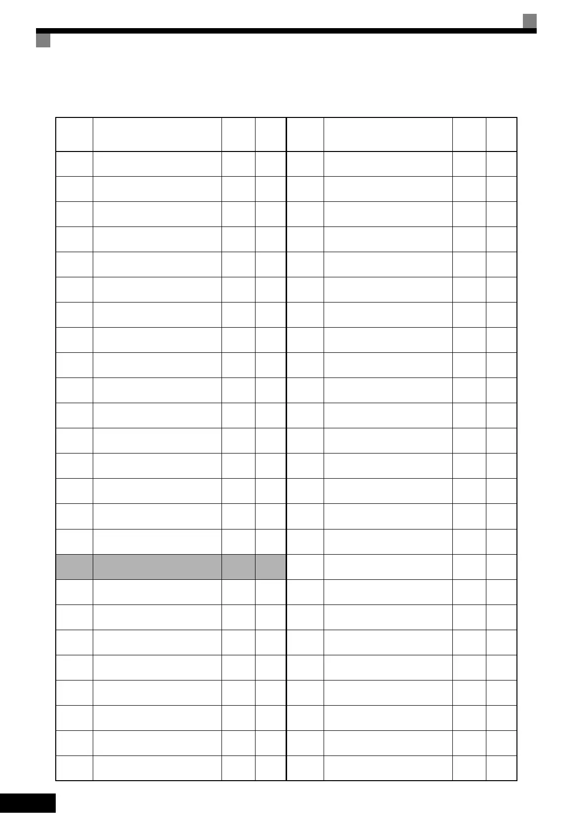
Table 10.9 User Constants (Continued)
E1-09 Min. output frequency
0.5
*2
E1-10 Min. output frequency voltage
2.0
*2 *9
E1-11 Mid. output frequency 2
0.0
*10
E1-12 Mid. output frequency voltage 2
0.0
*10
E1-13 Base voltage
0.0
*11
E2-01 Motor rated current
1.90
*6
E2-02 Motor rated slip
2.90
*6
E2-03 Motor no-load current
1.20
*6
E2-04 Number of motor poles 4
E2-05 Motor line-to-line resistance
9.842
*6
E2-06 Motor leak inductance
18.2
*6
E2-07 Motor iron saturation coefficient 1 0.50
E2-08 Motor iron saturation coefficient 2 0.75
E2-09 Motor mechanical loss 0.0
E2-10
Motor iron loss for torque compen-
sation
14
*6
E2-11 Motor rated output
0.40
*12
E2-12 Motor iron saturation coefficient 3 1.30
E3-01 Motor 2 control method selection 2
E3-02
Motor 2 max. output frequency
(FMAX)
60.0
E3-03 Motor 2 max. voltage (VMAX)
200.0
*2
E3-04
Motor 2 max. voltage frequency
(FA)
60.0
E3-05
Motor 2 mid. output frequency 1
(FB)
3.0
*2
E3-06
Motor 2 mid. output frequency
voltage 1 (VC)
11.0
*9
E3-07
Motor 2 min. output frequency
(FMIN)
0.5
*2
E3-08
Motor 2 min. output frequency
voltage (VMIN)
2.0
*9
No. Name
Fac-
tory
Setting
Set-
ting
E4-01 Motor 2 rated current
1.90
*6
E4-02 Motor 2 rated slip
2.90
*6
E4-03 Motor 2 no-load current
1.20
*6
E4-04
Motor 2 number of poles (number
of poles)
4
E4-05 Motor 2 line-to-line resistance
9.842
*6
E4-06 Motor 2 leak inductance
18.2
*6
E4-07 Motor 2 rated capacity
0.40
*12
F1-01 PG constant 600
F1-02
Operation selection at PG open cir-
cuit (PGO)
1
F1-03
Operation selection at overspeed
(OS)
1
F1-04 Operation selection at deviation 3
F1-05 PG rotation 0
F1-06
PG division rate (PG pulse moni-
tor)
1
F1-07
Integral value during accel/decel
enable/disable
0
F1-08 Overspeed detection level 115
F1-09 Overspeed detection delay time
0.0
*7
F1-10
Excessive speed deviation detec-
tion level
10
F1-11
Excessive speed deviation detec-
tion delay time
0.5
F1-12 Number of PG gear teeth 1 0
F1-13 Number of PG gear teeth 2 0
F1-14 PG open-circuit detection time 2.0
F2-01
Bi-polar or uni-polar input selec-
tion
0
F3-01 Digital input option 0
F4-01 Channel 1 monitor selection 2
F4-02 Channel 1 gain 1.00
No. Name
Fac-
tory
Setting
Set-
ting
TOE-S616-60.1.book 36 ページ 2017年8月4日 金曜日 午後3時41分

 Loading...


