Wiring Control Circuit Terminals
2-
33
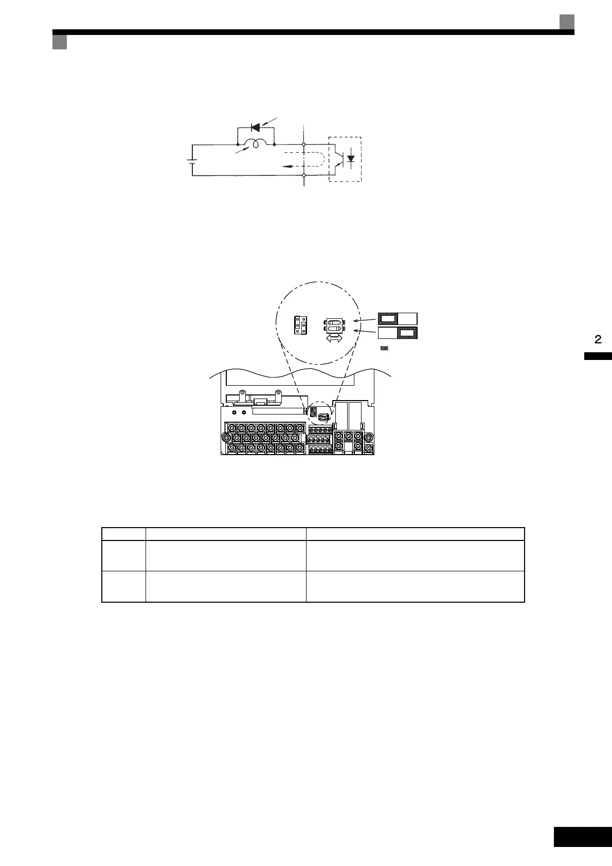
Fig 2.17 Flywheel Diode Connection
Shunt Connector CN5 and DIP Switch S1
The shunt connector CN 5 and DIP switch S1 are described in this section.
Fig 2.18 Shunt Connector CN5 and DIP Switch S1
The functions of DIP switch S1 are shown in the following table.
Sinking/Sourcing Mode
The input terminal logic can be switched between sinking mode (0-V common) and sourcing mode (+24-V
common) if shunt connector CN5 is used. An external 24-V power supply is also supported, providing more
freedom in signal input methods.
Table 2.12 DIP Switch S1
Name Function Setting
S1-1
RS-485 and RS-422 terminating resis-
tance
OFF: No terminating resistance
ON: Terminating resistance of 110 Ω
S1-2 Input method for analog input A2
OFF: 0 to 10 V, -10 to 10 V (internal resistance: 20 kΩ)
ON: 4 to 20 mA (internal resistance: 250 Ω)
External power:
48 V max.
Coil
Flywheel diode
50 mA max.
The rating of the flywheel diode
must be at least as high as the
circuit voltage.
Note: Refer to Table 2.12 for S1
functions and to Table
2.13 for CN5 functions.
: Factory settings
Terminating resistance
Analog input switch
TOE-S616-60.1.book 33 ページ 2017年8月4日 金曜日 午後3時41分

 Loading...


