Installing and Wiring Option Boards
2-
43
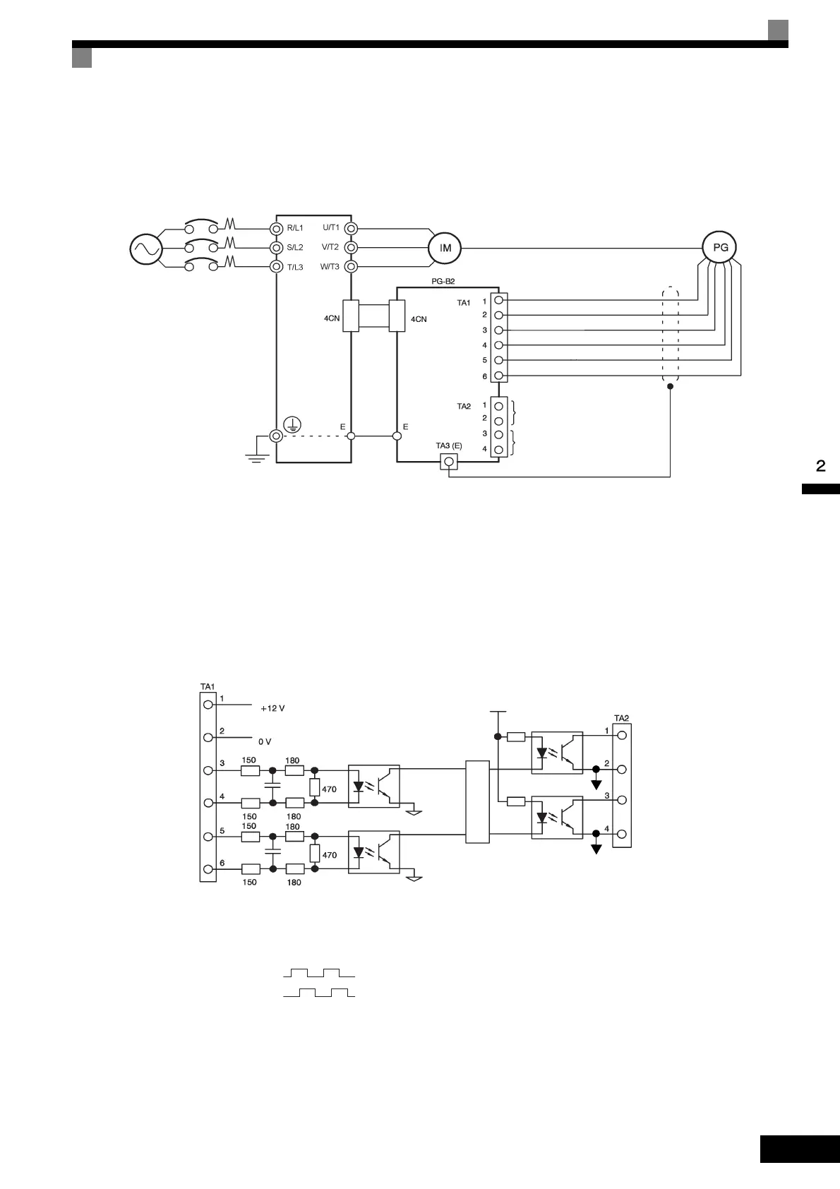
Wiring the PG-B2
Wiring examples are provided in the following illustrations for the PG-B2.
• Shielded twisted-pair wires must be used for signal lines.
• Do not use the pulse generator's power supply for anything other than the pulse generator (encoder).
Using it for another purpose can cause malfunctions due to noise.
• The length of the pulse generator's wiring must not be more than 100 meters.
• The direction of rotation of the PG can be set in user constant F1-05. The factory preset if for forward
rotation, A-phase advancement.
Fig 2.26 PG-B2 Wiring
• When connecting to a voltage-output-type PG (encoder), select a PG that has an output impedance with
a current of at least 12 mA to the input circuit photocoupler (diode).
• The pulse monitor dividing ratio can be changed using constant F1-06 (PG division rate).
• The pulse monitor emitter is connected to common inside the PG-B2. The emitter common must be used
for external circuits.
Fig 2.27 I/O Circuit Configuration of the PG-B2
Three-phase, 200
VAC (400 VAC)
Inverter
Power supply +12 V
Power supply 0 V
A-phase pulse output (+)
A-phase pulse output (-)
B-phase pulse output (+)
B-phase pulse output (-)
A-phase pulse monitor output
B-phase pulse monitor output
PG power
supply +12 V
A-phase pulse
input
B-phase pulse
input
A-phase
pulses
B-phase
pulses
Division rate circuit
B-phase pulse
monitor output
A-phase pulse
monitor output
A-phase pulses
B-phase pulses
TOE-S616-60.1.book 43 ページ 2017年8月4日 金曜日 午後3時41分

 Loading...


