2
-44
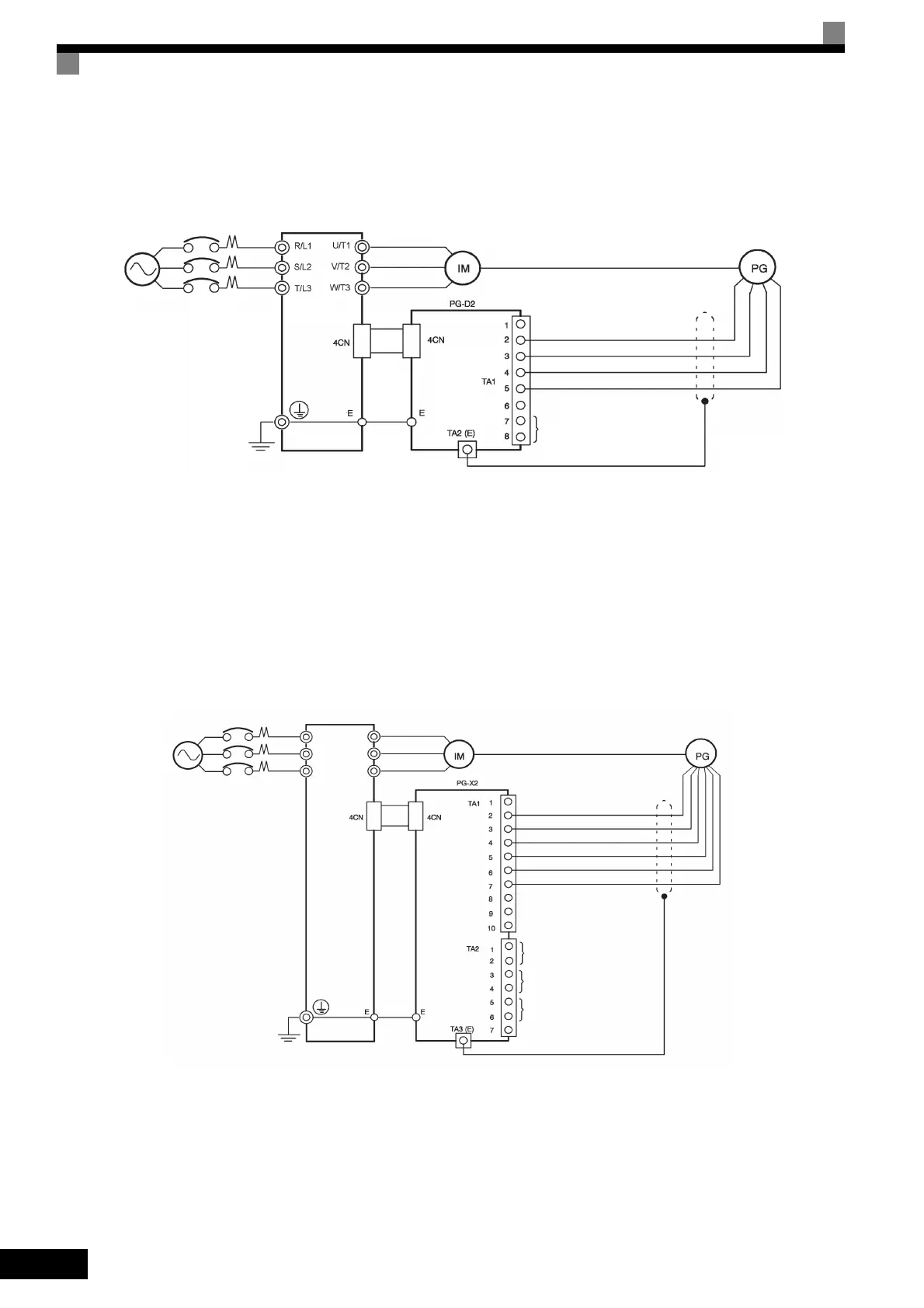
Wiring the PG-D2
Wiring examples are provided in the following illustrations for the PG-D2.
• Shielded twisted-pair wires must be used for signal lines.
• Do not use the pulse generator's power supply for anything other than the pulse generator (encoder).
Using it for another purpose can cause malfunctions due to noise.
• The length of the pulse generator's wiring must not be more than 100 meters.
Fig 2.28 PG-D2 Wiring
Wiring the PG-X2
Wiring examples are provided in the following illustrations for the PG-X2.
• Shielded twisted-pair wires must be used for signal lines.
• Do not use the pulse generator's power supply for anything other than the pulse generator (encoder).
Using it for another purpose can cause malfunctions due to noise.
• The length of the pulse generator's wiring must not be more than 100 meters.
• The direction of rotation of the PG can be set in user constant F1-05 (PG Rotation). The factory preset if
for motor forward rotation, A-phase advancement.
Fig 2.29 PG-X2 Wiring
Three-phase, 200
VAC (400 VAC)
Inverter
Power supply +12 V
Power supply 0 V
Power supply +5 V
Pulse input + (A/B phase)
Pulse input - (A/B phase)
Pulse monitor output
Three-phase,
200 VAC (400
VAC)
Inverter
Power supply +12 V
Power supply 0 V
Power supply +5 V
A-phase pulse input (+)
A-phase pulse input (-)
B-phase pulse input (+)
B-phase pulse input (-)
A-phase pulse monitor output
B-phase pulse monitor output
Z-phase pulse monitor output
R/L1
S/L2
U/T1
V/T2
W/T3T/L3
TOE-S616-60.1.book 44 ページ 2017年8月4日 金曜日 午後3時41分

 Loading...


