184
FREF2(n025)
FREF3(n026)
FREF4(n027)
FREF5(n028)
FREF6(n029)
FREF7(n030)
FREF8(n031)
FREF9(n120)
FREF10(n121)
FREF11(n122)
FREF12(n123)
FREF13(n124)
FREF14(n125)
FREF15(n126)
FREF16(n127)
FJOG(n032)
n164
100%
n129
n132
n132
- n134
n134
n133
n163
100%
-100%
200%
-200%
110%
0%
n132
n128 = 1, 3, 5, 7
Z
-1
Z
-1
Z
-1
Z
-1
Z
-1
+
+
+
+
+
++
+
+
++
+
+
+
-
+
+
+
-
-
-
n128 = 2, 4, 6, 8
1
n131
1
n135
n128
= 5, 6, 7, 8
n128 = 3, 4, 7, 8
× 1
× -1
Frequency reference
selection from DeviceNet
DeviceNet
transmission
DeviceNet
transmission
n004
n008
FREF1(n024)
FREF1(n024)
Transmission/
Control circuit
terminal switch
0: Remote/Local
1: DeviceNet
NetRef
0: Remote/Local
1: DeviceNet
0 Others
0 Others
1
1
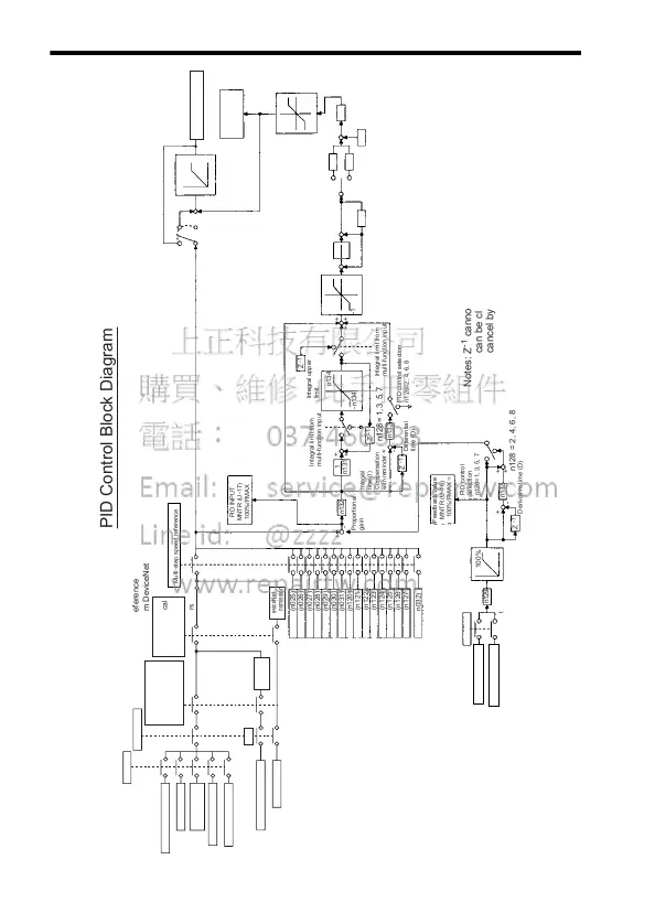
Notes: Z
-1
cannot be cleared during operation command input. Z
-1
can be cleared during stop command input, or during PID
cancel by the multi-function input.
Frequency reference
selection
Remote/Local
Adjustment
gain
Derivative time (D)
PID control
selection
n128=1, 3, 5, 7
Feedback value
MNTR (U-16)
100%/FMAX
PID INPUT
MNTR (U-17)
100%/FMAX
Integral
time (I)
Compensation
with reminder
Proportional
gain
Differential
time (D)
Integral limit from
multi-function input
Integral limit from
multi-function input
Integral upper
limit
PID control selection
n128=2, 4, 6, 8
PID primary delay time
constant compensation
with reminder
PID control selection
n128=1, 2, 3, 4
PID offset adjustment
PID output gain
PID output value
MNTR (U-18)
100%/FMAX
n128=1, 2, 5, 6 PID
control selection
n128=0 or PID cancel by a
multi-function input
Operator potentiometer
DeviceNet
communications
Operator (0 to 10 V)
Operator (4 to 20 mA)
Operator potentiometer
PID Control Block Diagram
Multi-step speed reference
Operator (0 to 10 V)
Operator (4 to 20 mA)
Output frequency