60
* 1. The speed scale can be set with AC/DC Drive object attribute 16 through
explicit message communications.
* 2. The speed reference setting cannot exceed the Inverter’s Maximum Out-
put Frequency Setting in constant n011.
* 3. When using the speed reference, always set the Number of Motor Poles (2
to 39) in Inverter constant n035 (Selecting Setting/Display Units of Fre-
quency Reference).
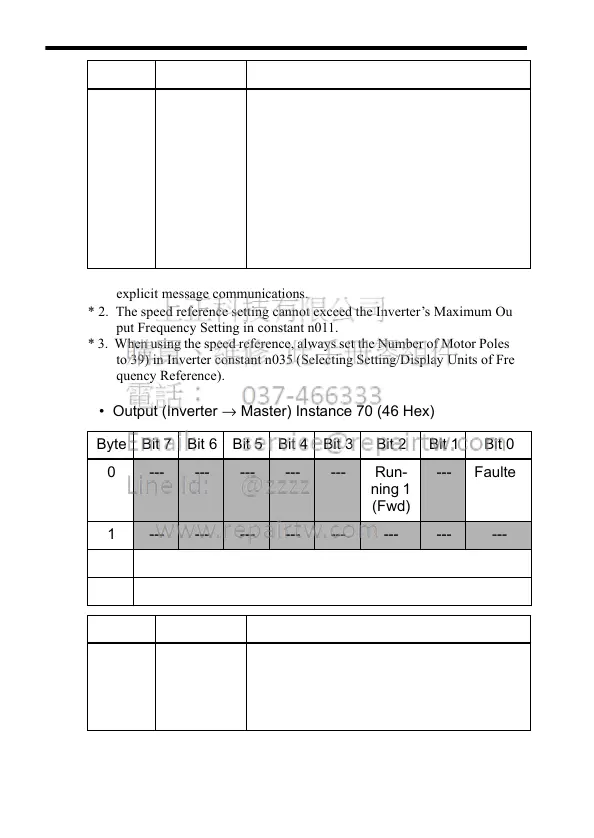
• Output (Inverter → Master) Instance 70 (46 Hex)
Bytes
2 and 3
Speed
Reference
*3
Sets the Inverter’s speed reference.
Speed reference data:
Frequency reference (r/min) × 2
SS
(
SS
: Speed scale
*1
)
Setting range: 0 to FFFF Hex
*2
For example, when setting a reference
of 1,800 r/min with a speed scale of 0:
Speed reference data = 1,800 × 2
0
=
1,800 = 0708 Hex
Byte Bit 7 Bit 6 Bit 5 Bit 4 Bit 3 Bit 2 Bit 1 Bit 0
0 --- --- --- --- --- Run-
ning 1
(Fwd)
--- Faulted
1 --- --- --- --- --- --- --- ---
2 Speed Actual (Low Byte)
3 Speed Actual (High Byte)
Data Name Contents
Byte 0,
bit 0
Faulted Indicates that the Inverter detected a
fault.
0: Normal
1: Fault detected.
Data Name Contents