6. Operating with DeviceNet Communications
85
Byte 0,
bit 7
Faulted Indicates that the Inverter detected a
fault.
0: Normal
1: Fault detected.
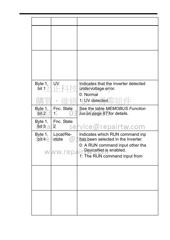
Byte 1,
bit 0
OPE Indicates that the Inverter detected a
MEMOBUS constant setting error
(OPE).
0: Normal
1: OPE (OP1 to OP5) detected.
Byte 1,
bit 1
UV Indicates that the Inverter detected an
undervoltage error.
0: Normal
1: UV detected.
Byte 1,
bit 2
Fnc. State
1
See the table MEMOBUS Function Sta-
tus on page 87 for details.
Byte 1,
bit 3
Fnc. State
2
Byte 1,
bit 4
Local/Re-
mote
Indicates which RUN command input
has been selected in the Inverter.
0: A RUN command input other than
DeviceNet is enabled.
1: The RUN command input from
DeviceNet is enabled.
Byte 1,
bit 5
Te r min al
MA*
Indicates the output status of Inverter
multi-function output terminal MA.
0: Terminal MA OFF
1: Terminal MA ON
Byte 1,
bit 6
Te r min al
P1
Indicates the output status of Inverter
multi-function output terminal P1.
0: Terminal P1 OFF
1: Terminal P1 ON
Data Name Contents