B2-16
IM 34M06H62-02E 2nd Edition : June 2008-00
SP-related Function Settings
Use these parameters to define set points for individual loops, as required. They can be
used for setting upper and lower input limits, rate-of-change, and tracking.
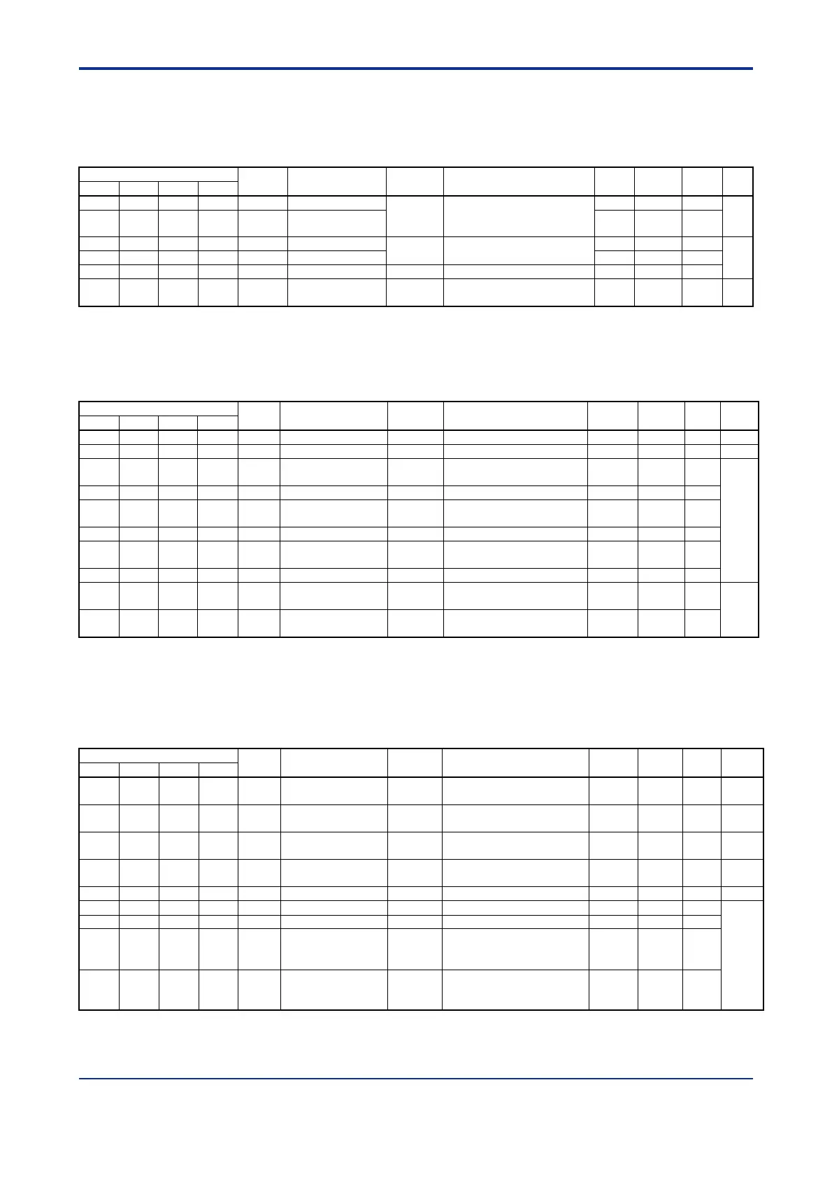
Table B2.19 SP-related Function Settings
Data Position Number
Symbol Description Unit
Data Range
Default
Value
Attribute Stored
See
Also
Loop 1 Loop 2 Loop 3 Loop 4
164 364 564 764 SPH Upper SP limit
Industrial
PRL to PRH if SPL < SPH
CSP is fixed at SPL if SPL
SPH
PRH RW
C4.3
165 365 565 765 SPL Lower SP limit PRL RW
166 366 566 766 SPR.UP SP up gradient
Industrial
0 to (PRH-PRL)
0: SP gradient disabled
0 RW
C4.4167 367 567 767 SPR.DN SP down gradient 0 RW
168 368 568 768 SPR.TM Gradient time unit None 0: Hour, 1: Minute 0 RW
169 369 569 769 SP.TR SP tracking mode None
0: Tracking enabled
1: Tracking disabled
1 RW C4.6
PV-related Function Settings
Use these parameters to perform PV-related setup for individual loops, as required. They
can be used for configuring PV correction, square root extraction and input filtering.
Table B2.20 PV-related Function Settings
Data Position Number
Symbol Description Unit Data Range
Default
Value
Attribute Stored
See
Also
Loop 1 Loop 2 Loop 3 Loop 4
171 371 571 771 BS Fixed bias Industrial -(SH-SL) to (SH-SL) 0 RW C3.8
172 372 572 772 FL Input filter Seconds 0: OFF, 1 to 120 seconds 0 RW C3.10
173 373 573 773 X1 Broken-line input 1 Industrial
-5.0% to 105.0% of (SL to
SH)
SL RW
C3.7
174 374 574 774 Y1 Broken-line bias 1 Industrial -(SH-SL) to (SH-SL) 0 RW
175 375 575 775 X2 Broken-line input 2 Industrial
-5.0% to 105.0% of
(SL to SH)
SL RW
176 376 576 776 Y2 Broken-line bias 2 Industrial -(SH-SL) to (SH-SL) 0 RW
177 377 577 777 X3 Broken-line input 3 Industrial
-5.0% to 105.0% of
(SL to SH)
SL RW
178 378 578 778 Y3 Broken-line bias 3 Industrial -(SH-SL) to (SH-SL) 0 RW
179 379 579 779 SR
Square root
extraction
None 0: OFF; 1: ON 0 RW
C3.9
180 380 580 780 LC Low cut Industrial 0.0 to 5.0% of (SH-SL))
1.0% of
(SH -SL)
RW
Operation-related Function Settings
Use these parameters to configure control operation for individual loops, as required.
They can be used to set up dynamic auto-tuning, the “super” function, control mode, and
other control operation-related functions.
Table B2.21 Operation-related Function Settings
Data Position Number
Symbol Description Unit Data Range
Default
Value
Attribute
Stored
See
Also
Loop 1 Loop 2 Loop 3 Loop 4
181 381 581 781 SELF
Dynamic
auto-tuning enable
None 0: Disabled, 1: Enabled 0 RW C5.1
182 382 582 782 SC
"Super" enable
code
None 0: Disabled, 1: Enabled 0 RW C6.7
183 383 583 783 ARW ARW setting %
0: Automatic, 500 to 2000:
(50.0 to 200.0%)
0 RW C6.8
184 384 584 784 CMD Control mode None
0: Standard PID control
1: Fixed-point control
0 RW C6.6
185 385 585 785 ZONE Zone PID selection None 0: Disabled, 1: Enabled 0 RW C6.9
186 386 586 786 1RP Reference point 1 Industrial PRL to PRH PRL RW
C6.9.2
187 387 587 787 2RP Reference point 2 Industrial PRL to PRH PRL RW
188 388 588 788 RHY
Zone switching
hysteresis
Industrial 0 to (PRH-PRL)
(PRH -
PRL) x
0.5%
RW
189 389 589 789 RDV
Reference
deviation
Industrial
0 to (PRH-PRL)
0: Reference deviation
disabled
0 RW

 Loading...