B2-17
IM 34M06H62-02E 2nd Edition : June 2008-00
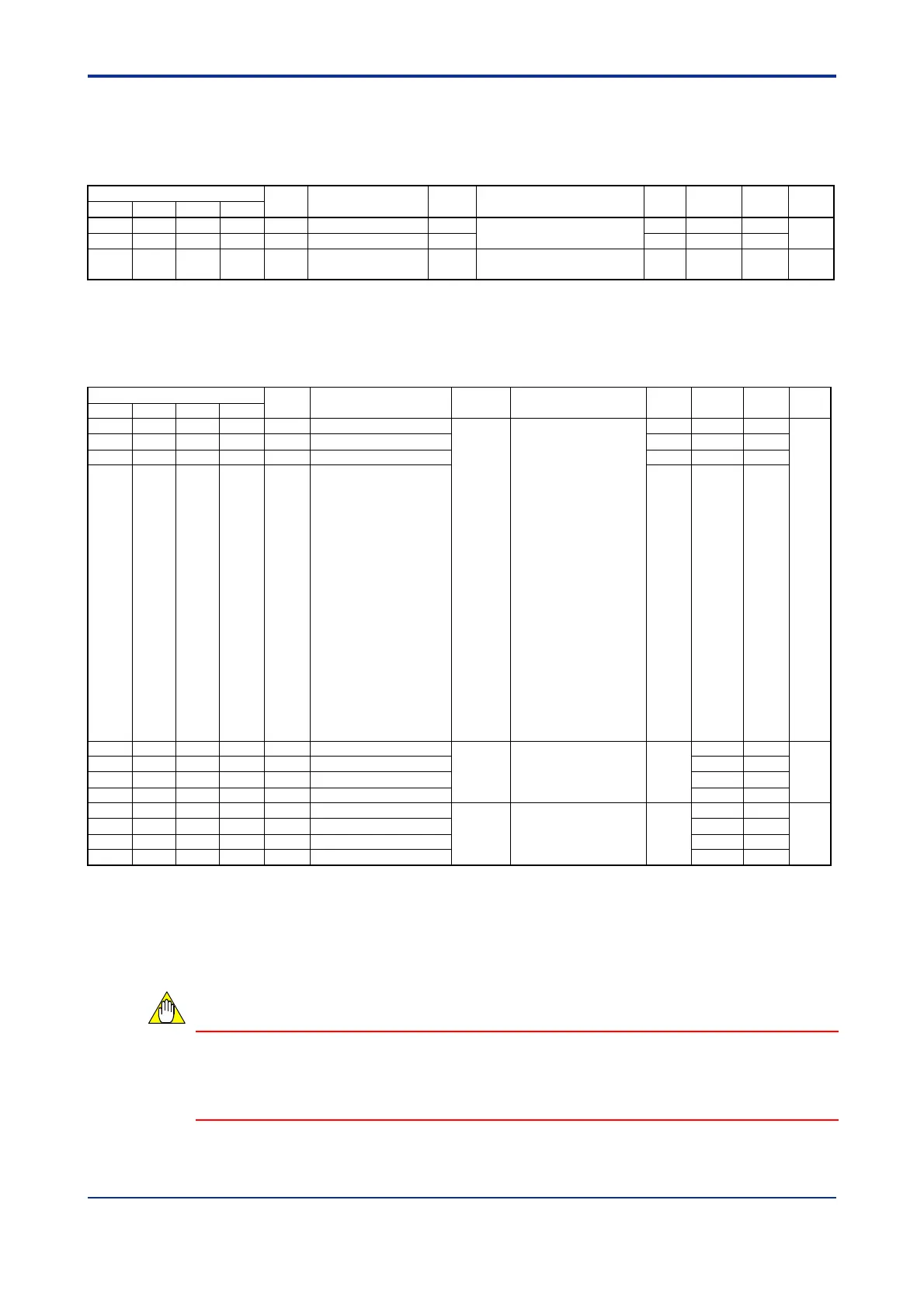
Output-related Function Settings
Use these parameters to configure control output for individual loops, as required. They
can be used for setting control output cycle time and rate-of-change limits.
Table B2.22 Output-related Function Settings
Data Position Number
Symbol
Description Unit Data Range
Default
Value
Attribute Stored
See
Also
Loop 1 Loop 2 Loop 3 Loop 4
191 391 591 791 CT Cycle time s
5 to 1200
(0.5 to 120.0 s)
300 RW
C2.4.2
192 392 592 792 CTc Cooling cycle time s 300 RW
193 393 593 793 MVR Rate-of-change limit
% per
second
0: Disabled
1 to 1000 (0.1 to 100.0%/s)
0 RW C2.4.2
Alarm-related Function Settings
Use these parameters to set up the operation of the alarm functions for individual loops
as required. They can be used to set up the alarm type, hysteresis, and ON delay timer.
Table B2.23 Alarm-related Function Settings
Data Position Number
Symbol Description Unit Data Range
Default
Value
Attribute Stored
See
Also
Loop 1 Loop 2 Loop 3 Loop 4
281 481 681 881 AL1 Alarm 1 type
None
0: OFF
1: Upper limit
2: Lower limit
3: Upper deviation
limit
4: Lower deviation
limit
7: Upper/lower
deviation limit
8: Deviation range
11: Upper limit with
waiting
12: Lower limit with
waiting
13: Upper deviation
limit with waiting
14: Lower deviation
limit with waiting
17: Upper/lower
deviation limit with
waiting
18: Deviation range
with waiting
1 RW
C8.1
C8.2
282 482 682 882 AL2 Alarm 2 type 2 RW
283 483 683 883 AL3 Alarm 3 type 1 RW
284 484 684 884 AL4 Alarm 4 type 2 RW
285 485 685 885 HY1 Alarm 1 hysteresis
Industrial
unit
0 to (PRH-PRL)
(PRH
- PRL)
x
0.5%
RW
C8.1
286 486 686 886 HY2 Alarm 2 hysteresis RW
287 487 687 887 HY3 Alarm 3 hysteresis RW
288 488 688 888 HY4 Alarm 4 hysteresis RW
289 489 689 889 DLY1 Alarm 1 ON delay
Second 0 to 999 (0 to 999 s) 0
RW
C8.3
290 490 690 890 DLY2 Alarm 2 ON delay RW
291 491 691 891 DLY3 Alarm 3 ON delay RW
292 492 692 892 DLY4 Alarm 4 ON delay RW
PID Parameters
Use these parameters to configure PID control-related functions for individual loops.
They can be used for specifying set points, alarm preset values, proportional band,
integral time, and derivative time. Up to four parameter groups can be defined for each
loop.
You need to execute a specific procedure every time to update stored set point values.
Otherwise, stored set points will not be updated so the parameters revert to their last
stored values whenever the module is turned off and then on again. For details, see
Section B2.4, "How to Back up SP Values to EEPROM."
CAUTION

 Loading...