1. Overview
26
TI 11B08A01-01E
• Externalsampleconditioningequipment
• Personal computer
• Computerforuppersystem,Analogequipment
• Analyzer network system
Thesystemcongurationmaydifferaccordingtothespecications.
SeetheGeneralSpecicationsfordetails.
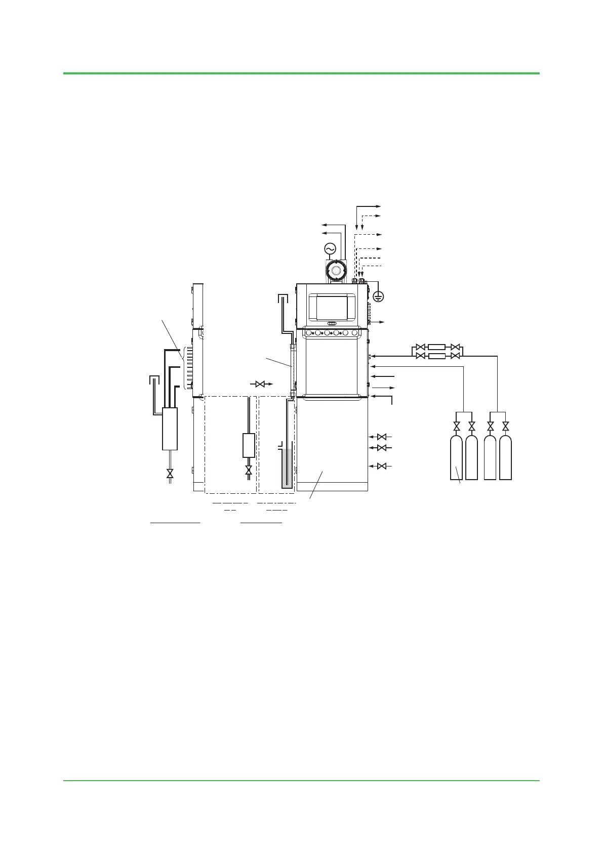
1.1 Wiring and Piping Diagram
Vent line
(1/8 inch 316SS pipes
for standard,
1/4 inch teflon tube
for FID/FPD)
Without Vent stack
50A
SGP, STPG
15A SPG, STPG
Vent stack
50A
SGP, STPG
15A
SPG,
STPG
Vent stack
ID:10mm
or more
Vent header
(Both ends are
Rc1/2 or 1/2NPT)
Liquid sample
50A
Water
seal
pot
15A SPG, STPG
Drain
*7
Drain tank
*4 *6
Analyzer base
sampling unit
(Depends on specifications)
Calibration standard
sample
Dehumidifier
Combustion air for FID/FPD
(400 to 700 kPa)
Instrument air
(350 to 900kPa)
(500 to 900 kPa for FPD)
(Spare)
(Spare)
Carrier gas
Grounding resistance 100Ω or less
Ethernet communication *10
Power
Serial communication (RS-422) *10
Analog input (4 to 20mA/1 to 5V DC), up to 16 *10
Contact input (5V DC, 20mA DC or more), up to 32
Analog output (4 to 20mA DC)
Channel isolation or System isolation, up to 32
Contact output (AC or DC), up to 20 *10
Air output for Stream switching valve
(350 kPa), up to 8
Air output for
Atmospheric balance
valve (350 kPa)
Contact output for System alarm 1
Contact output for Annunciator
*1
*2
*8
*5
*9
*3
*11
*4
*4
Combustion gas or
Make-up gas for FID/FPD
With Vent stack
Sample
…
Sample
Using a water
seal pot
Using a drain
tank
*1: ThespecicationdeterminesthenumberofExplosionproofenclosures.NoenclosuresisneededforFM-Y,
CSA-Y type.
*2: Ifananalyzerbasesamplingunitisprovided,mostapplicationsrequirenoexternalsamplingequipment.
In addition, optimum sampling systems are prepared depending on various conditions. (For details, consult
Yokogawa. Optimal sampling systems will be offered.)
*3: Forairpurgepiping,usestainlesssteelpipeof1/2inchormore.
*4: Powerandcontactoutputforsystemalarm1orannunciatorareconnectedtocontrolunitincaseofFM-Y,
CSA-Y type.
*5: DehumidiercanbeoptionallyprovidedbyYokogawa.Otherwiringcables,pipingandinstallationmaterials
should be supplied by the user.
*6: Circuitbreaker(30ATorless)shallbesuitablefortheitemofthepowersupplydescribedinthe
specication,andlocatedneartheanalyzer.
*7: DraintankisneededonlyforGCsusingFID/FPD.ThisisnotusedforGCsusingTCD.
*8: Fixventingpipesproperlysothattheloadoftheventingpipesdoesnotapplytotheassemblingventsof
this analyzer.
*9: Thenumberofstreamsincludingoneforcalibrationstandardsampleisasfollows,incaseofusingGCSMP.
Type 1: Maximum of 7
Type 2, 4: Maximum of 4
*10: Signalinterrupters(disconnecters)arerequireddependingonthespecication.
*11: Airpressuresetvalueoftheregulatorisdependedonthesourceairtemperatureandneedtotunethe
setting value.
600kPaisrequiredwhenambientorinstrument-airtemperatureishigherthan46°C(1FPD)or40°C(2FPDs).
Sep. 07, 2017-00

 Loading...
