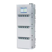
Do you have a question about the YOKOGAWA GC8000 and is the answer not in the manual?
| Brand | YOKOGAWA |
|---|---|
| Model | GC8000 |
| Category | Laboratory Equipment |
| Language | English |
Lists necessary user manuals and operation data for the GC8000 system.
Provides guidance on manual usage, reproduction, and error reporting.
Details safety instructions, symbol meanings, and prohibition of unauthorized modification.
Describes various labels on the GC8000 related to safety and protection types.
Critical warnings regarding gas hazards, instrument weight, and handling.
Cautions for lifting, carrying, avoiding impact, and cleaning the instrument.
Details GC8000 explosion protection standards and types.
Identifies key components of the analyzer for explosionproof types.
Instructions for operating door fasteners and locks.
Warnings and procedures for handling the protection system.
Safety measures and requirements when using hydrogen gas.
Guidelines for selecting and preparing the installation location.
Safety warnings and precautions for FM wiring.
Safety warnings and precautions for CSA wiring.
Safety warnings and precautions for ATEX, IECEx, NEPSI wiring.
Safety warnings and precautions for TIIS wiring.
Procedures for maintenance and inspection of the GC8000.
Explanation and usage of the override function.
Methods for checking pressure in pressurized enclosures.
Safety warnings and cautions during instrument operation.
Step-by-step procedures for powering the GC8000 on and off.
Specific power procedures for FM-Y and CSA-Y models.
Response procedures for low pressure in enclosure sections.
Specific safety guidelines for ATEX, IECEx, and NEPSI compliance.
Details on safety system components and their specifications.
Notes on safety system installation and wiring.
Procedures to follow in case of an emergency involving the safety system.
Requirements for maintaining safety function through proof testing.
Conditions and procedure for replacing the safety system.
Overview of equipment used to construct a GC8000 system.
Dimensions and connection points for Type 1 wall-mounted GC8000.
Dimensions and connection points for Type 1 self-standing GC8000.
Dimensions and connection points for Type 2 wall-mounted GC8000.
Dimensions and connection points for Type 2 self-standing GC8000.
Dimensions and connection points for Type 3 wall-mounted GC8000.
Dimensions and connection points for Type 3 self-standing GC8000.
Dimensions and connection points for Type 4 wall-mounted GC8000.
Dimensions and connection points for Type 4 self-standing GC8000.
Dimensions and connection points for Type 5 wall-mounted GC8000.
Dimensions and connection points for Type 5 self-standing GC8000.
Recommended space for maintenance and operation access.
Details on piping connections for the GC8000 control unit.
Details on piping connections for oven units.
Diagrams showing piping connections for the GCSMP.
General guidelines for connecting pipes for the GC8000.
Dimensions and types of rack-mounted communication converters and interrupters.
Dimensions and types of desk-top communication converters.
Description of gas cylinders, regulators, and stop valves.
Function and installation of dehumidifiers and vent stacks.
Types of pipings and joints used for the GC8000.
Requirements for sample, carrier, and standard gases.
Specifications for hydrogen gas and instrument air.
Requirements for combustion air and steam.
Details of the data plate for FM-X and FM-Y models.
Details of the data plate for CSA-X and CSA-Y models.
Data plate parameters for ATEX models.
Data plate parameters for IECEx models.
Data plate parameters for NEPSI models.
Procedures for installing the analyzer.
Instructions and warnings for unpacking the GC8000.
Checking for damage and verifying model/suffix codes.
List of accessory kits and their contents.
Securing the analyzer to the floor or wall.
Installation of auxiliary hardware like cylinders and vent stacks.
Details on various piping types and general installation guidelines.
General guidelines for connecting pipes for the GC8000.
Requirements for sample, standard, and carrier gas inlet pipes.
Requirements for instrument air, combustion air, and hydrogen gas piping.
Piping requirements for steam supply and venting systems.
Piping for steam drain and external sampling system valves.
Table of protection system counts based on specifications.
Lists and diagrams of required wiring types and connection points.
Cable temperature recommendations based on class and ambient temperature.
Detailed table of wiring connections, cable types, and terminals.
Important notes on cable arrangement and wiring precautions.
Specific wiring warnings and cautions for FM specification.
Specific wiring warnings and cautions for CSA specification.
Wiring warnings and cautions for ATEX, IECEx, NEPSI.
Wiring instructions and precautions for TIIS specification.
Instructions for connecting cables to the protection system.
Table for selecting packing based on cable O.D. and torque.
Instructions for connecting cables to the electronics section.
Table for selecting packing for electronics section based on cable O.D.
Safety notes and procedures for power and grounding cable connections.
Table specifying crimp-on terminals for power and grounding.
Details on power supply lines for protection systems A and B.
Power supply connections for the electronics section.
Instructions for independent grounding of the GC8000.
General cautions and cable temperature requirements for signal cables.
Cautions and guidelines for signal cable termination.
Wiring for the external I/O cutoff signal.
Wiring diagrams for alarm and annunciator contact outputs.
Cable temperature requirements and connection diagram for Ethernet.
Cable temperature requirements and connection diagram for optical fiber Ethernet.
Instructions for wiring to the GC8000 card slots.
Wiring diagrams for serial communication cards.
Wiring diagrams for analog output cards.
Wiring diagrams for analog input cards.
Wiring diagrams for AC contact output cards.
Wiring diagrams for DC contact output cards.
Wiring diagrams for contact input cards.
Wiring diagrams for AC contact input/output cards.
Wiring diagrams for DC contact input/output cards.
 Loading...