2. Installation, Piping, and Wiring
77
TI 11B08A01-01E
2.3.4 Connecting Power Cable and Grounding
CAUTION
• Wire the power supply cable keeping the distance of 1 cm or more from other signal wires.
• The power supply cable shall comply with UL or CSA.
• Do wiring after securing protective grounding.
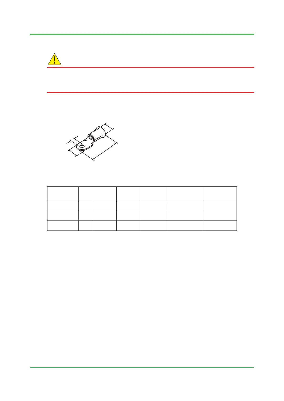
Use crimp-on terminals for all power cables and grounding (see Figure 2.20).
Use crimp-on terminals suitable for the cable core (see Table 2.8).
Lug length c
inside diameter d
Hole
diameter
a
Lug outside
diameter b
Figure 2.20 Crimp-on terminal
Table 2.8 Size of crimp-on terminal
Nominal cross
sectional area
Screw
(mm)
Hole
diameter a
(mm)
Outside
diameter b
(mm)
Length c
(mm)
Insulation
covering inside
diameter d (mm)
Applicable
terminal*
5.5 mm
2
4 4 to 5 9.8 or less 25 to 29 5.8 or less
AMP 170785-1
JST 5.5-4
2.0 mm
2
4 4.3 or more 8.7 or less approx. 21 5.8 or less
AMP 170782-1
JST V2-4
1.25 mm
2
4 4.3 or more 8.7 or less approx. 21 5.8 or less
AMP 170782-1
JST V1.25-4
*: AMP:JapanAMPCo.,Ltd.
JST: JST Co., Ltd.
l Power supply line to the protection system (A) (B)
The power supply to protection system A is used for both heater power and electric circuit power.
The power supply or protection system B is used only for heater power.
ConnecttheattachedferritecoreforATEX,IECExorNEPSI.
Grounding must be wired.
Pleasedonotforgettoputprotection-lmcover,afterwiringisnished.
Sep. 07, 2017-00

 Loading...
