2. Installation, Piping, and Wiring
85
TI 11B08A01-01E
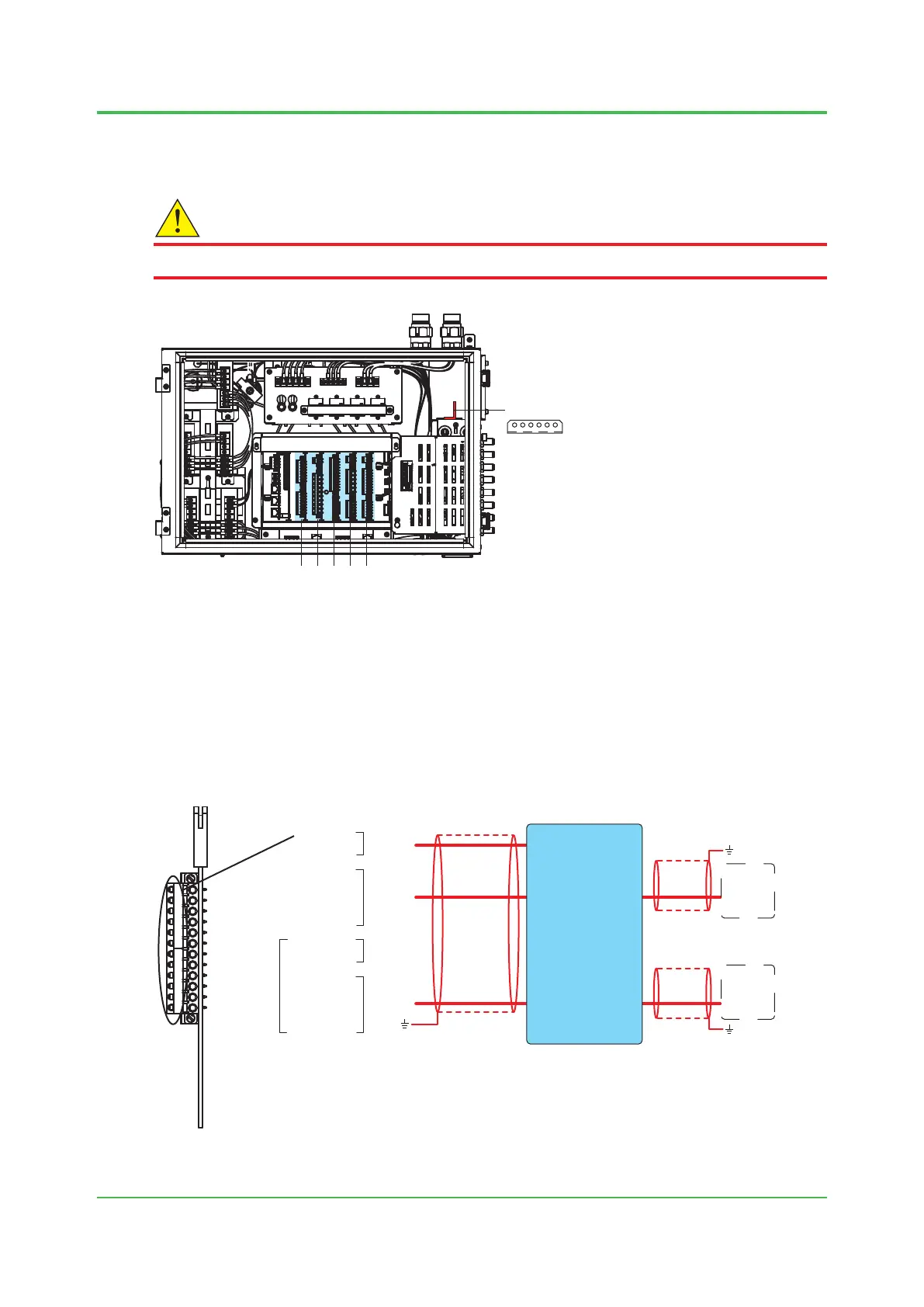
n Wiring to slots 1 to 5
Perform wiring to slots 1 to 5 for each card.
CAUTION
After the card is removed, return it to its original position. There is a label on the card.
Slot 1
Slot 2
Slot 3
Slot 4
Slot 5
Earth bar
Figure 2.27
FKC series terminals from Phoenix Contact Ltd. are used.
For these wiring connections, use AI series crimp-on terminals from the same company. Check if
the crimp-on terminals meet wire diameters in Table 2.5.
l Serialcommunication(1ch)(Code:C)andserialcommunication(2ch)(Code:
D) (H) (L)
1
2
3
4
5
6
7
8
9
10
11
12
1
2
3
4
5
6
7
8
9
10
11
12
V1 +
V1 -
TxD1 +
TxD1 -
RxD1 +
RxD1 -
24V DC
RS-422
(L)
V2 +
V2 -
TxD2 +
TxD2 -
RxD2 +
RxD2 -
24V DC
RS-422
(H)
(H)
1 V +
2 V -
11 Rx1 +
12 Rx1 -
13 Tx1 +
14 Tx1 -
15 Rx2 +
16 Rx2 -
17 Tx2 +
18 Tx2 -
Tx1 + 21
Tx1 - 22
Rx1 + 23
Rx1 - 24
Tx2 + 25
Tx2 - 26
Rx2 + 27
Rx2 - 28
Signal interrupter K9806AE
RS-422
RS-422
*1: This is not used for FM-Y, CSA-Y.
*2: The ground wire is connected to the earth bar.
*3: The ground wire is connected to the earth terminal on site.
*1
*3
*1
*1
*2
For 2ch
Figure 2.28 Wiring for serial communication cards
Sep. 07, 2017-00

 Loading...
