2. Installation, Piping, and Wiring
66
TI 11B08A01-01E
WARNING
IncaseofTIIS-certiedwiring,theattachedcablepackingadaptersorsealingttingmustbe
used.
Otherwise, it does not comply with TIIS regulation.
CAUTION
• Lay the signal wiring and electrical wiring in separate conduit pipes or ducts.
• Useindependentgroundingwith a grounding resistance of 100 ohms or less.
2.3.1 Types of Wiring and Locations
ThefollowingtypesofwiringarerequiredfortheGC8000.
Thewiringrequiredvarieswiththespecications.
(A) Electric circuit and heater power
(B) Heater power
(C) Contact output for system alarm 1
(D) Contact output for annunciator
(E) Analog input (4 to 20 mA)
(F) Contactinput(Operationstart/stop,mode-selectionrequest,etc.)
(G) Contact output
(H) Communication wiring (RS-422 and analyzer bus)
(J) Analog output (4 to 20 mA), Analog hold output
(K) Grounding
(L) External I/O cutoff output (Power cutoff signal)
(M) Ethernet (twisted-pair cable)
(N) Ethernet(opticbercable)
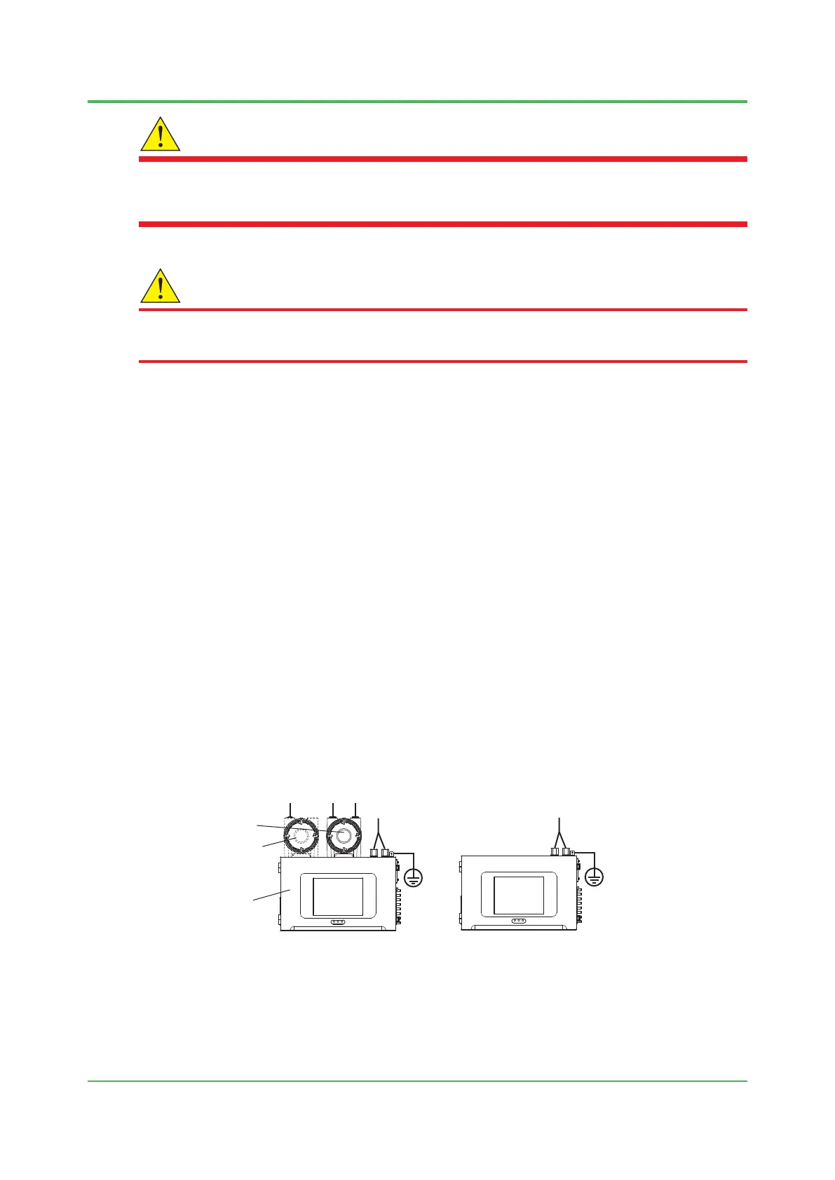
B A
K
CD EFGH
JLMN
K
ABCDEFGH
JLMN
Protection system A
Control unit
Protection system B *
* Protection system B is equipped in some specifications.
With protection system Without protection system
Figure 2.12 Cable connection locations
Sep. 07, 2017-00

 Loading...
